Vapor compression refrigerating cycle apparatus

a refrigerating cycle and vapor compression technology, applied in the direction of refrigerating machines, lighting and heating apparatus, fluid circulation arrangement, etc., can solve the problems of difficult to achieve the improvement of the cop sufficiently, and the efficiency of the ejector is improved, and the input energy applied to the ejector is reduced, the effect of increasing the pressur

Active Publication Date: 2009-09-17
DENSO CORP
View PDF15 Cites 11 Cited by
  • Summary
  • Abstract
  • Description
  • Claims
  • Application Information

AI Technical Summary

Benefits of technology

[0009]Accordingly, since the flow rate of the refrigerant flowing into the nozzle portion of the ejector is adjusted in accordance with the heat load, pressure energy as ejector input energy can be adjusted. As such, it is possible to appropriately ensure an increase in pressure by the ejector. Therefore, ejector efficiency is improved, and hence the COP of the refrigerating cycle apparatus is improved.
[0010]For example, the flow distributor is configured to be capable of adjusting dryness of the refrigerant of the first passage to be smaller than dryness of the refrigerant of the second passage in a first load condition where the heat load is lower than a predetermined load. In general, an increase in pressure by the ejector increases as a ratio of a flow rate of the refrigerant drawn into the suction portion to a flow rate of the refrigerant flowing into the nozzle portion reduces. In the first load condition, a flow rate of the refrigerant circulating through the refrigerating cycle apparatus is reduced, and thus input energy applied to the ejector is reduced. As a result, the increase in pressure by the ejector is reduced. Considering such a circumstance, since the dryness of the refrigerant of the first passage is adjusted smaller than the dryness of the refrigerant of the second passage in the first load condition, the flow rate of liquid-phase refrigerant passing through the first passage is increased. Therefore, the flow rate ratio is reduced, and hence the increase in pressure by the ejector is increased. Accordingly, even in the first load condition, ejector efficiency is sufficiently maintained and the increase in pressure is ensured. As a result, the COP of the refrigerating cycle apparatus improves.
[0011]In a second load condition where the heat load is higher than the predetermined load, for example, the dryness of the refrigerant of the first passage is adjusted larger than the dryness of the refrigerant of the second passage. In the second load condition, the flow rate of the refrigerant circulating through the refrigerating cycle apparatus is increased. If the flow rate of the refrigerant flowing in the nozzle portion is excessively increased, expansion of the refrigerant in the nozzle portion is likely to be insufficient. Thus, the nozzle efficiency is reduced, and energy recovery is reduced. As a result, input energy of the ejector reduces. Considering such a circumstance, since the dryness of the refrigerant of the first passage is adjusted larger than the dryness of the refrigerant of the second passage in the second load condition, the flow rate of the liquid-phase refrigerant passing through the first passage is reduced and thus the refrigerant can be appropriately expanded in the nozzle portion. As such, the nozzle efficiency improves. With this, the increase in pressure by the ejector is ensured and the COP of the refrigerating cycle apparatus is improved.

Problems solved by technology

In a vapor compression refrigerating cycle apparatus having an ejector, it is difficult to sufficiently improve the COP due to a change in heat load of the refrigerating cycle apparatus.
Thus, it is difficult to sufficiently achieve the improvement of the COP of the refrigerating cycle apparatus.

Method used


Image

  • Vapor compression refrigerating cycle apparatus
  • Vapor compression refrigerating cycle apparatus
  • Vapor compression refrigerating cycle apparatus

Examples


first embodiment

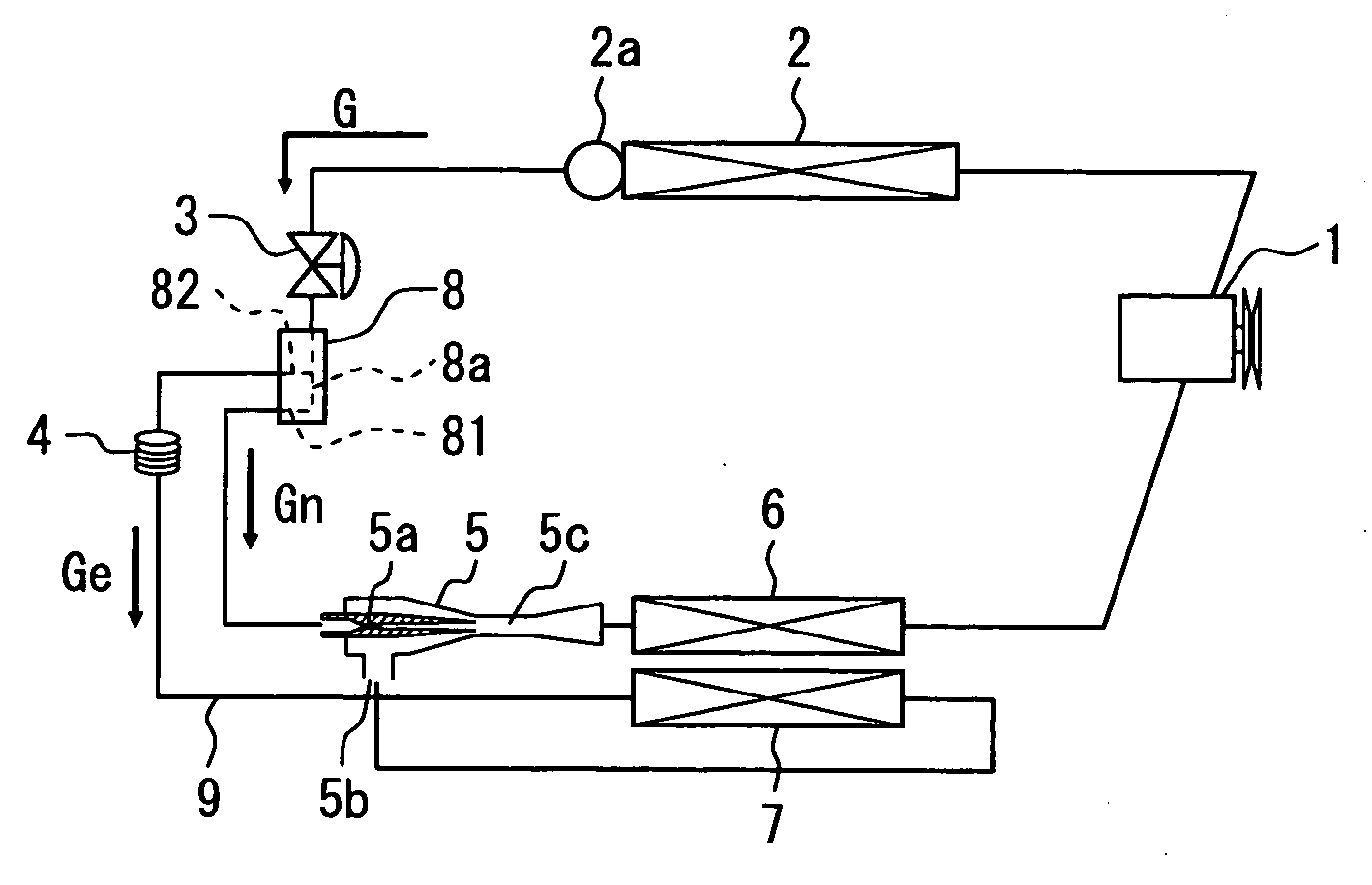
[0020]A first embodiment of the present invention will now be described with reference to FIGS. 1 to 5. FIG. 1 shows a vapor compression refrigerating cycle of the first embodiment. The vapor compression refrigerating cycle apparatus is, for example, mounted in a vehicle for an air conditioner.

[0021]The vapor compression refrigerating cycle apparatus generally includes a compressor 1, a radiator 2, a receiver 2a, a first throttle device 3, a flow distributor 8, an ejector 5, a first evaporator 6, a second evaporator 7 and a second throttle device 4. The compressor 1, the radiator 2, the receiver 2a, the first throttle device 3, the flow distributor 8, the ejector 5 and the first evaporator 6 are connected through refrigerant pipes in a form of loop. The refrigerating cycle apparatus further has a suction passage 9 diverging from the flow distributor 8 and connecting to the ejector 5. The second throttle device 4 and the second evaporator 7 are disposed on the suction passage 9. An o...

second embodiment

[0060]A second embodiment of the present invention will be hereinafter described.

[0061]In the first embodiment, the expansion valve 3, the capillary tube 4, the ejector 5, the first evaporator 6 and the flow distributor 8 are separately disposed from one another, but can be integrated as follows.

[0062]For example, the flow distributor 8 can be integrated with the expansion valve 3. As another example, the flow distributor 8 and the capillary tube 4 can be integrated with each other. As further another example, the flow distributor 8 and the ejector 5 can be integrated with each other. In such cases, devices around the flow distributor 8 are reduced in size. Therefore, mountability of the refrigerating cycle apparatus to the vehicle improves.

[0063]Further, the flow distributor 8, the ejector 5 and the first evaporator 6 can be integrated with each other. In such a case, since the first evaporator 6 is provided as a base device, individual spaces for mounting the flow distributor 8 an...


PUM


Abstract

A vapor compression refrigerating cycle apparatus includes a compressor, a radiator, first and second throttle devices, a flow distributor, an ejector, a suction passage, and first and second evaporators. The flow distributor separates refrigerant decompressed through the first throttle device into a first passage and a second passage. The first passage is in communication with a nozzle portion of the ejector. The second passage is in communication with a suction portion of the ejector through the suction passage. The second throttle device and the second evaporator are disposed on the suction passage. The flow distributor is configured to be capable of adjusting a ratio of a flow rate of refrigerant passing through the second passage to a flow rate of refrigerant passing through the first passage in accordance with a heat load of at least one of the radiator, the first evaporator and the second evaporator.

Description

CROSS REFERENCE TO RELATED APPLICATION[0001]This application is based on Japanese Patent Application No. 2008-64666 filed on Mar. 13, 2008, the disclosure of which is incorporated herein by reference.FIELD OF THE INVENTION[0002]The present invention relates to a vapor compression refrigerating cycle apparatus having an ejector as a refrigerant decompressing and circulating device.BACKGROUND OF THE INVENTION[0003]In a vapor compression refrigerating cycle apparatus, it is known to employ an ejector as a decompressing device for decompressing refrigerant, which has been compressed into a supercritical state by a compressor and cooled through a radiator. The ejector is, for example, described in JP-A-2004-116807.[0004]The ejector has a nozzle portion that converts pressure energy of the refrigerant flowing out from the radiator into velocity energy, thereby to isoentropically decompress and expand the refrigerant. Further, the ejector draws gas-phase refrigerant from in an evaporator b...

Claims


Application Information

Patent Timeline
Patent Type & Authority Applications(United States)
IPC IPC(8): F25B1/06F25B39/02
CPCF25B41/00F25B2500/19F25B2341/0011
Inventor YAMADA, ETSUHISANISHIJIMA, HARUYUKIOGATA, GOUTAGOCHO, MIKAKAYANO, KENTA
Owner DENSO CORP
Why Eureka
Try Eureka