
Device and method for sensing at least one partially specular surface

a technology of specular surface and sensing device, which is applied in the direction of photometry, photometry using electric radiation detector, instruments, etc., can solve the problems of limited spatial resolution, inconvenient use of said methods, and high cost of visual examination, etc., and achieve high resolution

Active Publication Date: 2016-06-16
FRAUNHOFER GESELLSCHAFT ZUR FOERDERUNG DER ANGEWANDTEN FORSCHUNG EV
View PDF8 Cites 25 Cited by
  • Summary
  • Abstract
  • Description
  • Claims
  • Application Information

AI Technical Summary

Benefits of technology

The present invention provides a method for detecting surface defects on a specular surface by projecting a pattern onto the surface and analyzing the reflection of the pattern using a camera. The detected pattern can be used to determine the surface defect. The method can be performed using both visual inspection and automatic inspection, without the need for step-by-step positioning of the measuring devices or surface. Additionally, in some embodiments, ultraviolet or extreme ultraviolet light can be used to improve the detection of surface defects.

Problems solved by technology

Said methods are not suitable in most cases for surfaces having a large or a very large amount of gloss.
In addition, they exhibit a limited spatial resolution and are not, or hardly, sensitive to small local differences in inclination of the surfaces as occur on above-mentioned surface defects of alloy wheels, for example.
Said visual examination may be very time-consuming and / or costly.
In addition, such visual examination is subjective and may not be reproducible and / or quantifiable in a reliable manner.
Fatigue or fluctuations in the ability to concentrate on the part of the human examiner may give rise to the risk of defect slippage.
Small or very small lacquer defects which have a small height extension, for example within the micrometer range, may possibly not be reliably sensed by means of the laser light-slit method.
The data transmission rate for transmitting two-dimensional camera pictures to a computer is currently limited, for technical reasons, to a maximum of 100 pictures / s, so that the object is typically moved discontinuously and so that a reduced testing throughput is achieved.
The useful step-wise positioning of the object, or of the surface, in relation to the metrological arrangement of the camera and the fluorescent or projection screen (or vice versa, of the metrological arrangement in relation to the object) may additionally involve a large amount of effort, i.e., may be costly and / or relatively slow, with regard to the mechanical components that may be used such as with regard to the axes of displacement that are to be realized.

Method used


Image

  • Device and method for sensing at least one partially specular surface
  • Device and method for sensing at least one partially specular surface
  • Device and method for sensing at least one partially specular surface

Examples


Embodiment Construction

[0024]Before embodiments of the present invention will be explained in detail below with reference to the figures, it shall be noted that elements, objects and / or structures that are identical, identical in function or identical in effect are provided with the same reference numerals in the different figures, so that the descriptions of said elements that are presented in different embodiments are interchangeable and / or mutually applicable.

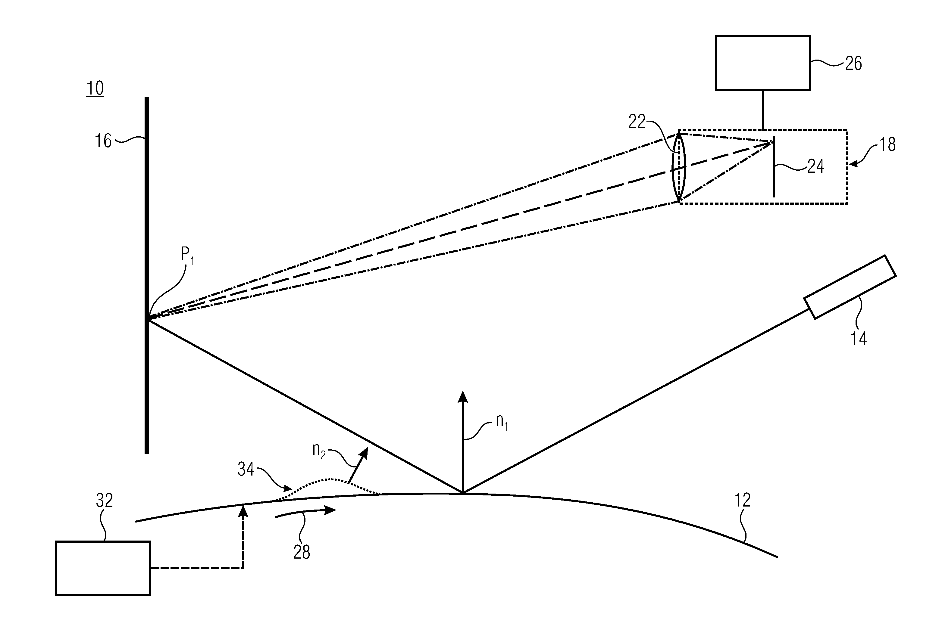
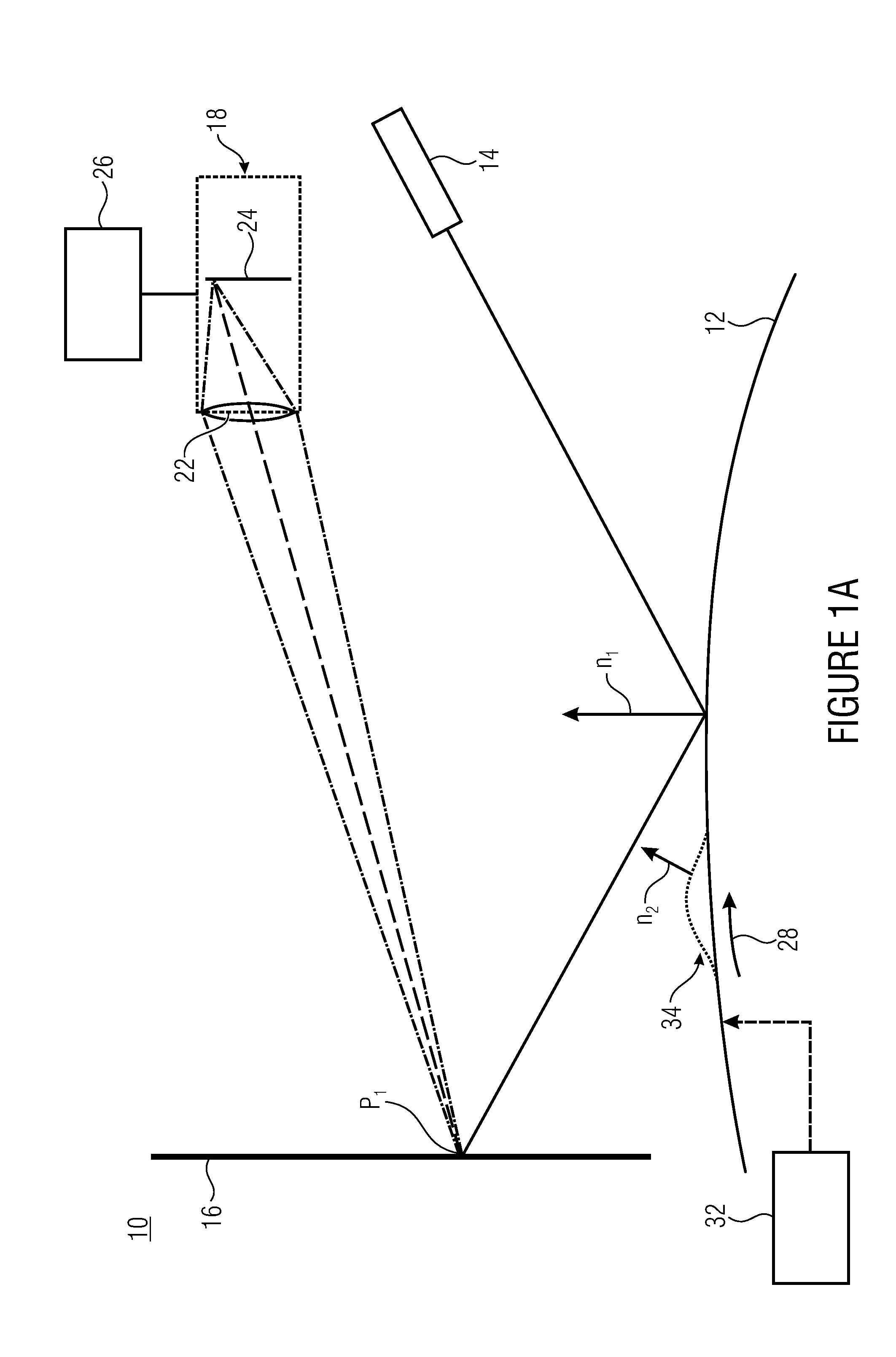
[0025]FIG. 1a shows a device 10 for sensing an at least partially specular surface 12. The at least partially specular surface 12 may be a surface of an alloy rim for car wheels or the like, a lacquered metal sheet or a mirror surface. A lacquered metal sheet may be a gloss-lacquered, transparently lacquered, metallically specular metal sheet. The at least partially specular surface may alternatively be a ceramic or glass surface that is to be measured and / or examined. Alternatively, the device 10 enables, e.g., eye glasses or other shiny technica...


PUM


Abstract

Among a device and a method for sensing at least partially specular surfaces, the device includes a detection face and an illuminator configured to project a pattern onto the detection face by reflection via the at least partially specular surface.

Description

CROSS-REFERENCE TO RELATED APPLICATIONS[0001]This application is a continuation of copending International Application No. PCT / EP2014 / 067733, filed Aug. 20, 2014, which claims priority from German Application No. 102013216566.8, filed Aug. 21, 2013, which are each incorporated herein in its entirety by this reference thereto.[0002]The present invention relates to a device for sensing at least partially specular surfaces and to a method of sensing same.BACKGROUND OF THE INVENTION[0003]For economic reasons, mainly contactless measuring methods are employed for inspecting glossy or high-gloss surfaces such as those of alloy wheels, for example, for surface defects such as dents, bumps, drops or bumps of lacquer (paint), scratches or grooves, for example. In the functional field of industry, surface defects are typically sensed and detected by means of optical capturing methods.[0004]With sufficiently cooperative, i.e., diffusely scattering, surfaces, shape measurement may also be affec...

Claims


Application Information

Patent Timeline
IPC IPC(8): G01N21/57
CPCG01N21/57G01N2201/061G01N2201/08G01N21/8806G01B11/2518
Inventor KOSTKA, GUENTHERSCHMITT, PETERHUEGEL, CHRISTIANSEIFERT, LARS
Owner FRAUNHOFER GESELLSCHAFT ZUR FOERDERUNG DER ANGEWANDTEN FORSCHUNG EV
Learn More