Antenna assembly with attachment fittings and associated methods

a technology of attachment fittings and antennas, applied in the field of antennas, can solve the problems of increasing the difficulty of designing a k-band/ku-band radome to meet desired structural and electrical performance characteristics, increasing the weight of metal plates, and increasing the cost of metal plates

Active Publication Date: 2016-06-16
THALES INC
View PDF4 Cites 11 Cited by
  • Summary
  • Abstract
  • Description
  • Claims
  • Application Information

AI Technical Summary

Benefits of technology

[0010]The attachment fittings may comprise at least one fore attachment fitting, at least one right side attachment fitting, at least one left side attachment fitting, and at least one aft attachment fitting. The at least one fore attachment fitting may be configured to react to vertical, lateral and longitudinal loads. The at least one right side attachment fitting may be configured to react to vertical loads and permit lateral and longitudinal displacement. The at least one left side attachment fitting may be configured to react to vertical loads and permit lateral and longitudinal displacement. The at least one aft attachment fitting may be configured to react vertical and lateral loads and permit longitudinal displacement. A fairing may mount the radome to the attachment fittings. Mounting of the antenna assembly directly to the fuselage with the attachment fittings advantageously avoids the need for a bulky and heavy mounting plate.
[0011]The fore attachment fittings may be fixed while the aft attachment fittings and the left and right side attachment fittings may be floating. As a result, the antenna assembly is light weight yet has the necessary strength to meet aerodynamic load requirements.
[0012]The fairing may have at least one vent opening therein. The antenna assembly may further comprise at least one airflow deflector carried by the fairing and cooperating with the at least one vent opening to lower a pressure within the radome during flight of the aircraft.

Problems solved by technology

As a result of such a wide bandwidth, it becomes more difficult to design a K-band / Ku-band radome to meet desired structural and electrical performance characteristics.
The use of a metal plate is bulky and heavy.
Although such a metal plate sized for a single satellite antenna may be acceptable, it becomes weight prohibitive when increased in size to cover more than one satellite antenna.

Method used


Image

  • Antenna assembly with attachment fittings and associated methods
  • Antenna assembly with attachment fittings and associated methods
  • Antenna assembly with attachment fittings and associated methods

Examples


Embodiment Construction

[0033]The present invention will now be described more fully hereinafter with reference to the accompanying drawings, in which preferred embodiments of the invention are shown. This invention may, however, be embodied in many different forms and should not be construed as limited to the embodiments set forth herein. Rather, these embodiments are provided so that this disclosure will be thorough and complete, and will fully convey the scope of the invention to those skilled in the art. Like numbers refer to like elements throughout.

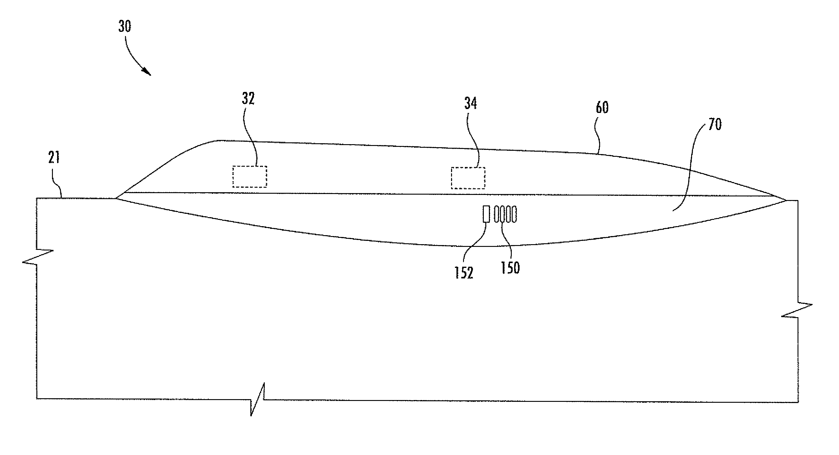
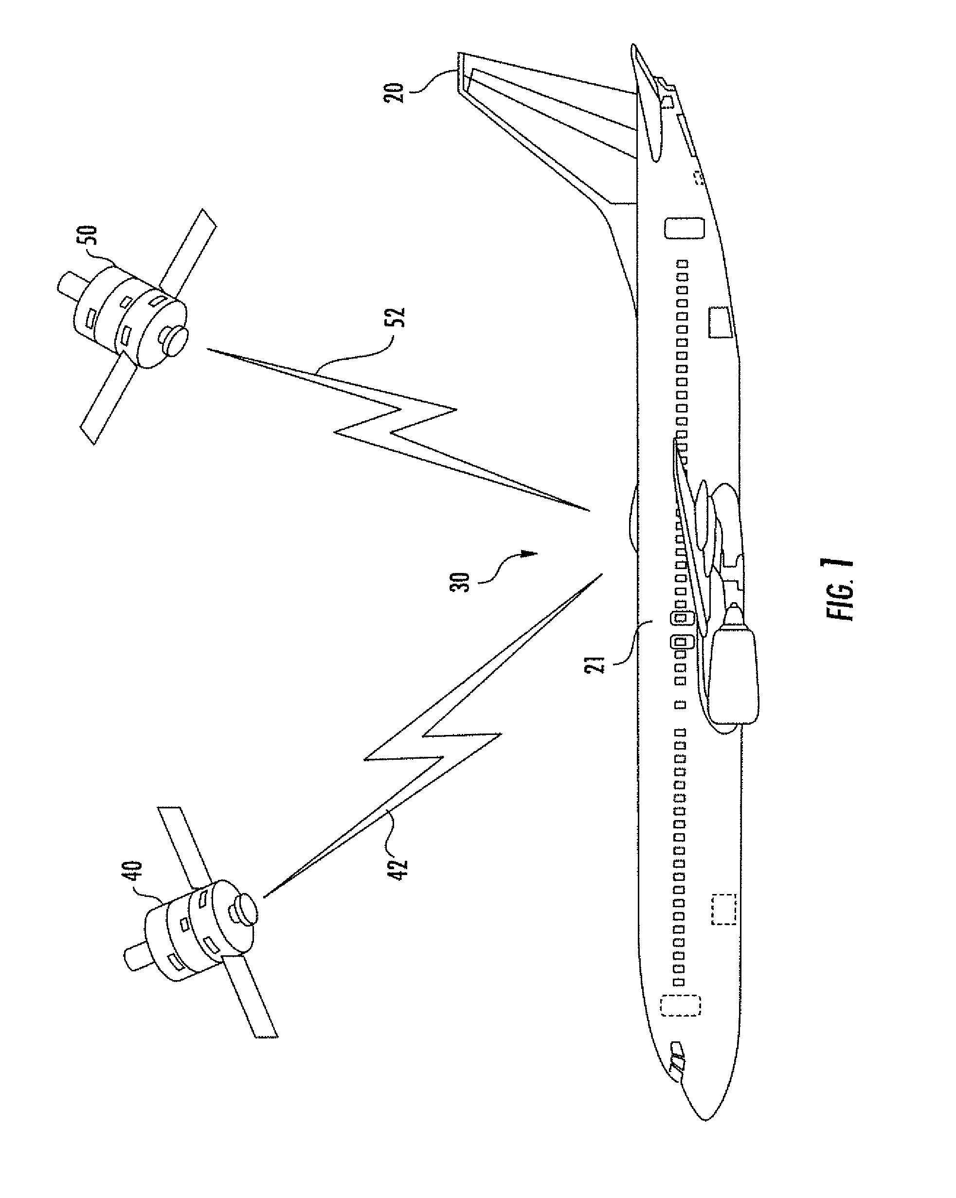
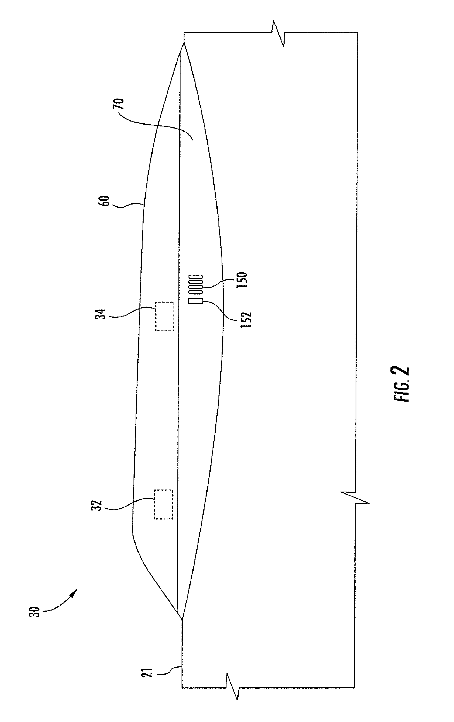
[0034]Referring initially to FIG. 1, an antenna assembly 30 is provided for a fuselage 21 of an aircraft 20. The antenna assembly 30 is configured to operate over a bandwidth of 12-40 GHz, which includes Ku-band, K-band and Ka-band. The aircraft 20 may be a commercial aircraft, for example. The illustrated antenna assembly 30 may simultaneously communicate with two different satellites 40, 50. The antenna assembly 30 may also simultaneously communicate wit...


PUM


Abstract

An antenna assembly is for a fuselage of an aircraft and includes a satellite antenna, a radome covering the satellite antenna, and attachment fittings for coupling to the fuselage of the aircraft. The attachment fittings include fore, aft and side attachment fittings. The fore attachment fittings react to vertical, lateral and longitudinal loads. The aft attachment fittings react to vertical and lateral loads and permit longitudinal displacement. Left side and right side attachment fittings react to vertical loads and permit lateral and longitudinal displacement. A fairing mounts the radome to the attachment fittings.

Description

FIELD OF THE INVENTION[0001]The present invention relates to the field of antennas, and more particularly, to an antenna assembly with attachment fittings for an aircraft, and related methods.BACKGROUND OF THE INVENTION[0002]Commercial aircraft typically include a satellite antenna for establishing a communication link with one or more geosynchronous satellites. The satellites may be a direct broadcast satellite (DBS) for providing television programming or a fixed satellite service (FSS) providing Internet access, for example. A DBS satellite operates within 12.2-12.7 GHz, and a FSS satellite operates within 11.7-12.2 GHz. These frequencies are within the Ku-band.[0003]An antenna assembly carried by the aircraft includes a radome to protect the satellite antenna and associated equipment from environmental exposure. The radome needs to be strong to withstand the aerodynamic loads of the aircraft while meeting desired electrical performance characteristics. A bandwidth of a Ku-band s...

Claims


Application Information

Patent Timeline
Patent Type & Authority Applications(United States)
IPC IPC(8): H01Q1/28H01Q1/42H01Q1/50
CPCH01Q1/28H01Q1/42H01Q1/50
Inventor KEEN, R. MICHAELMCCUNE, WILLIAM DAVIDANDERSON, BRIAN D.
Owner THALES INC
Why Eureka
Try Eureka