Solar power plant

a solar power plant and solar panel technology, applied in photovoltaics, solar heat collectors for particular environments, heat collector mounting/support, etc., can solve the problem of high price of weatherproof solar power plants, prevent soiling of surfaces, prevent damage to solar panels, and prevent soiling

Inactive Publication Date: 2016-06-16
DHP TECH
View PDF3 Cites 20 Cited by
  • Summary
  • Abstract
  • Description
  • Claims
  • Application Information

AI Technical Summary

Benefits of technology

[0028]The cleaning system advantageously includes at least one mechanical cleaning system, a cleaning by means of liquid or by means of compressed air and monitoring sensors for recording the cleanliness. These systems make it possible for the solar power plant to be cleaned automatically, if the fronts of the solar panels 19 are soiled. The principle can function similarly to a windscreen wiper of a passenger car.
[0029]It has also proven to be advantageous, if a protection device, in particular, a net or a tarpaulin-like canopy is located between support posts. The support posts can serve as a retaining element for a bird or hail net. A surface area used agriculturally beneath the solar power plant is, therefore, protected against bird feeding and precipitations. The protection device or the net can be clamped long-term or can be located on an end support capable of being rolled up.
[0030]A further aspect of the invention relates to a method for the prevention of soiling of the surfaces of the solar panels in order to prevent damage to the solar panels of a solar power plant by wind, snow or ice loading, in which the solar panels

Problems solved by technology

Such solar power plants have the disadvantage that they form a large engagement area for

Method used


Image

  • Solar power plant
  • Solar power plant
  • Solar power plant

Examples


Embodiment Construction

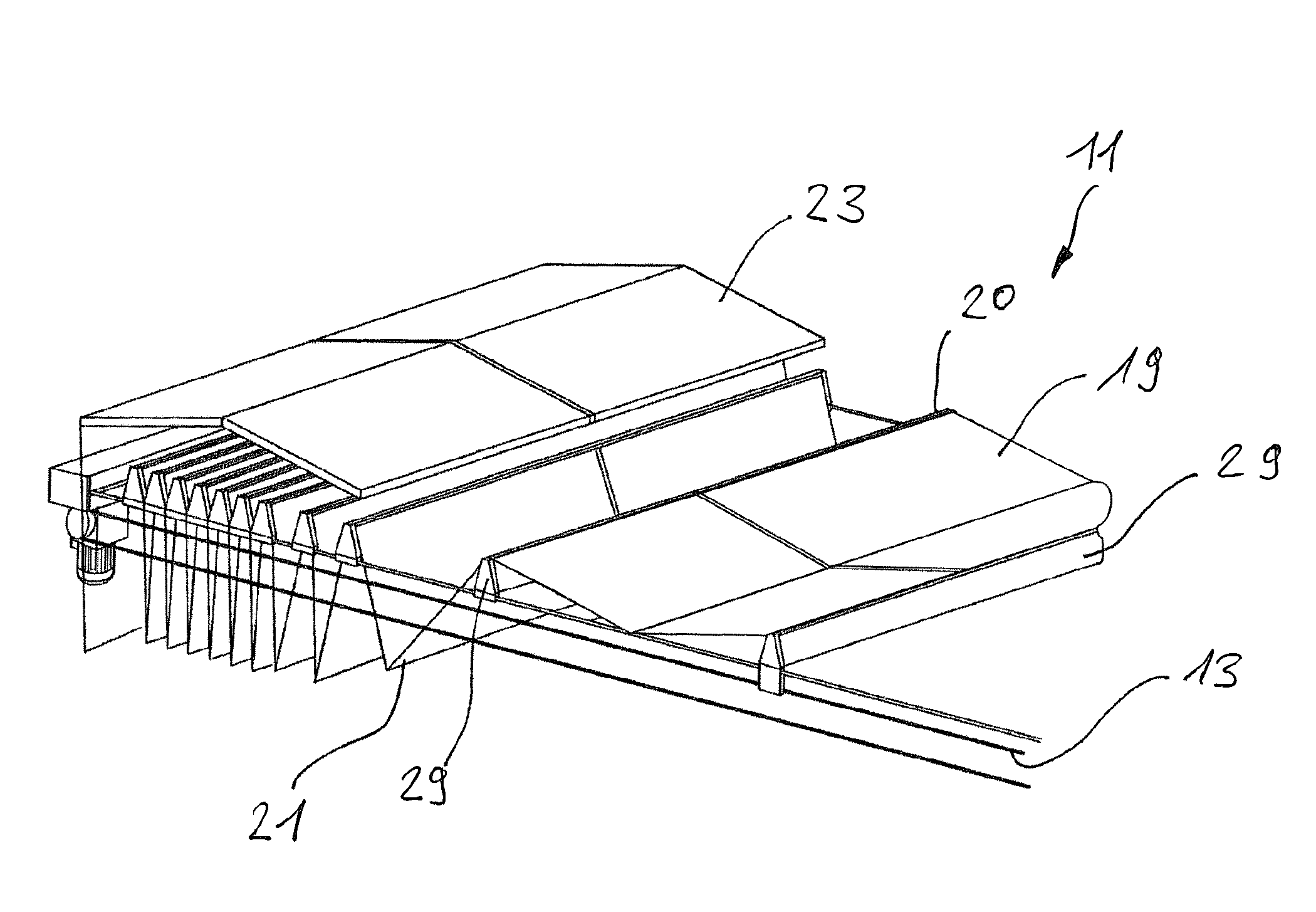
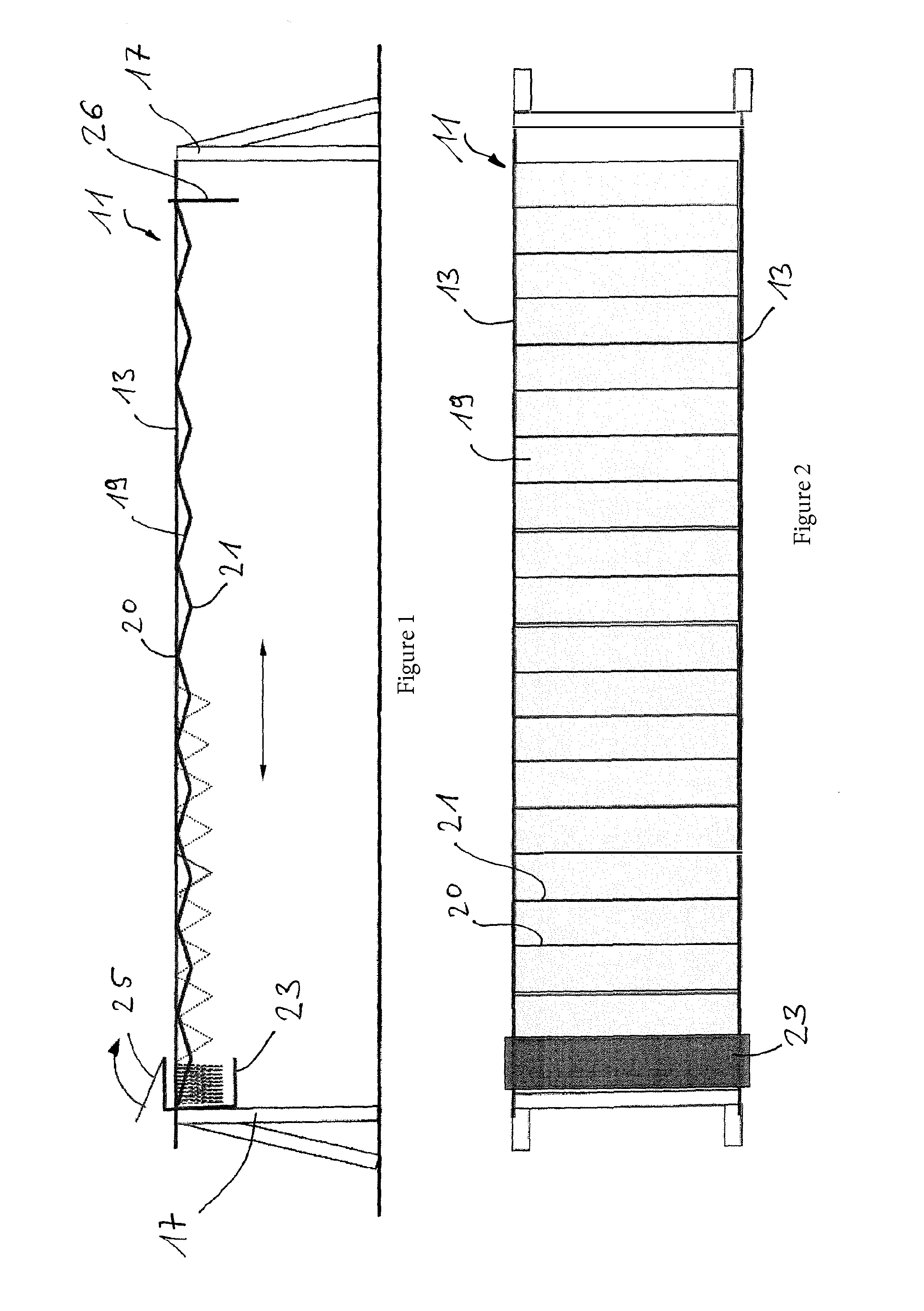
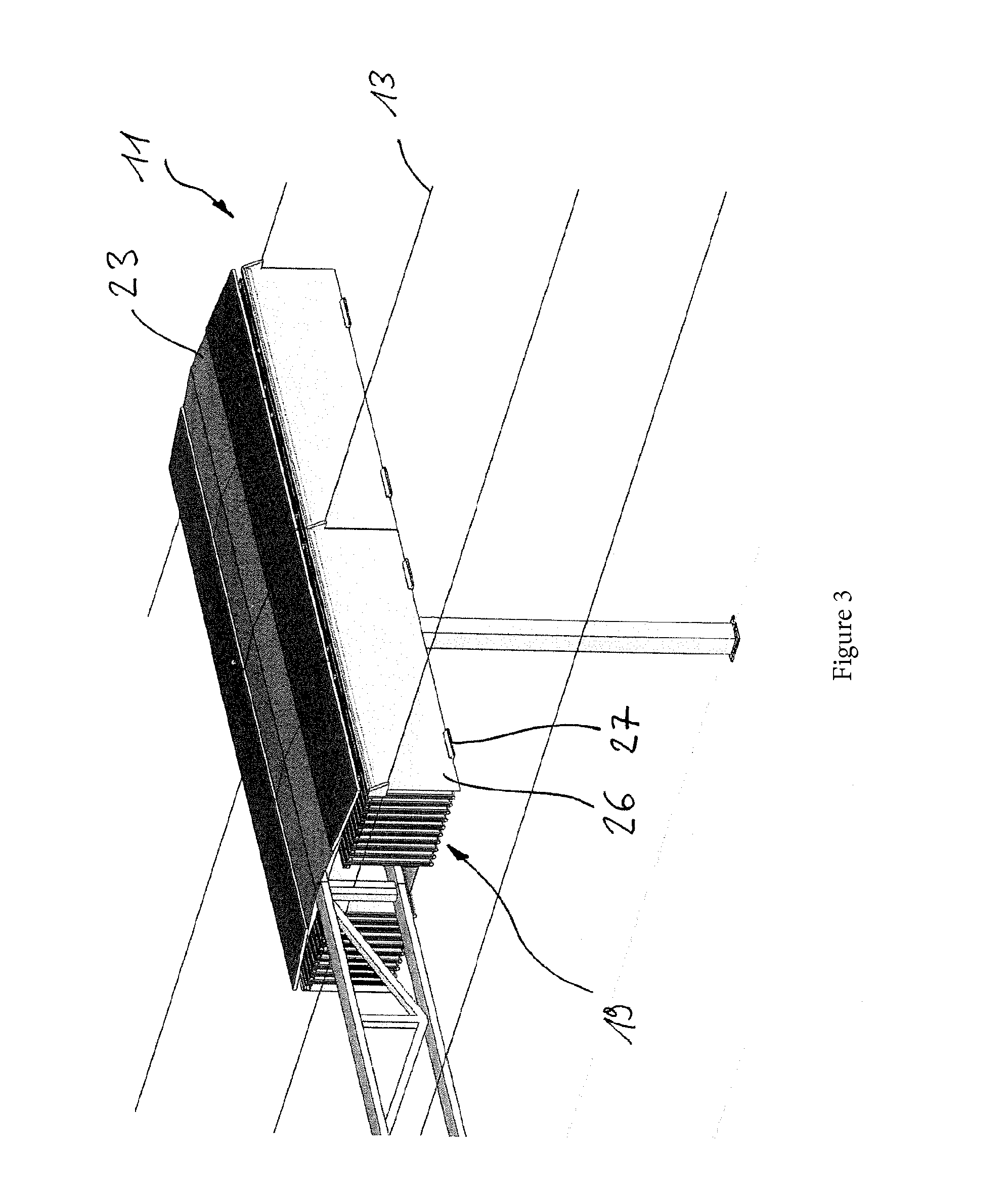
[0040]FIGS. 1 and 2 show an embodiment of the solar power plant according to the present invention, which is designated as a whole with the reference sign 11. In this embodiment two essentially parallel running guide ropes or guide rods 13 are provided as retaining elements. The guide ropes or rods 13 are stretched or run between two posts 17. It would also be conceivable, that the guide rods 13 are located on a flat surface area, for example, on a roof, without posts 17 being used.

[0041]A plurality of solar panels 19 arranged in a row is held on the guide ropes or guide rods 13. If in the framework of this application a solar panel 19 is spoken of, then a plate with two essentially parallel flat sides is thus disclosed, wherein a plurality of photovoltaic cells is arranged on at least one flat side. FIGS. 1 and 3 show adjacent solar panels 19 that are connected to each other in a jointed manner. The jointed connection can be designed, for example, as a hinge 20, wherein bushings 22...


PUM


Abstract

The invention relates to a solar power plant having a plurality of solar panels arranged in a row and at least one holding element on which the solar panels are held one after the other. The solar panels can be displaced along the at least one holding element with engagement means from an extracted operating position into a retracted resting position.

Description

CROSS-REFERENCE TO RELATED APPLICATIONS[0001]This application is a national phase entry under 35 U.S.C. §371 of PCT / CH2013 / 000208 filed on Dec. 3, 2013, which claims priority to European Patent Application 13166708.1 filed on May 6, 2013, the entirety of each of which is incorporated by this reference.FIELD OF THE INVENTION[0002]The invention relates to a solar power plant.PRIOR ART[0003]Solar power plants are known from the prior art, for example, WO 2010 / 006460, in which solar panels are swivel-mounted on ropes stretched between two support posts. Such solar power plants have the disadvantage that they form a large engagement area for wind and snow. The supporting structure must accordingly be designed sturdily, so that wind and weather cannot damage the solar power plant. Accordingly, such a sturdy weather-resistant solar power plant is expensive.[0004]Solar modules are known from JP 2003318430, which are connected by pairs of hinges provided on opposite sides. The plurality of s...

Claims


Application Information

Patent Timeline
IPC IPC(8): H02S30/20H02S20/20
CPCH02S20/20H02S30/20Y02E10/47F24S40/85F24S30/20F24S20/50F24S40/10F24S25/50F24S30/00Y02E10/50
Inventor BAUMGARTNER, FRANZBUCHEL, ARTHUR
Owner DHP TECH
Why Eureka
Try Eureka