

Water Injection and Venting of a Plasma Arc Torch
- Summary
- Abstract
- Description
- Claims
- Application Information
AI Technical Summary
Benefits of technology
Problems solved by technology
Method used
Image

Examples
Embodiment Construction
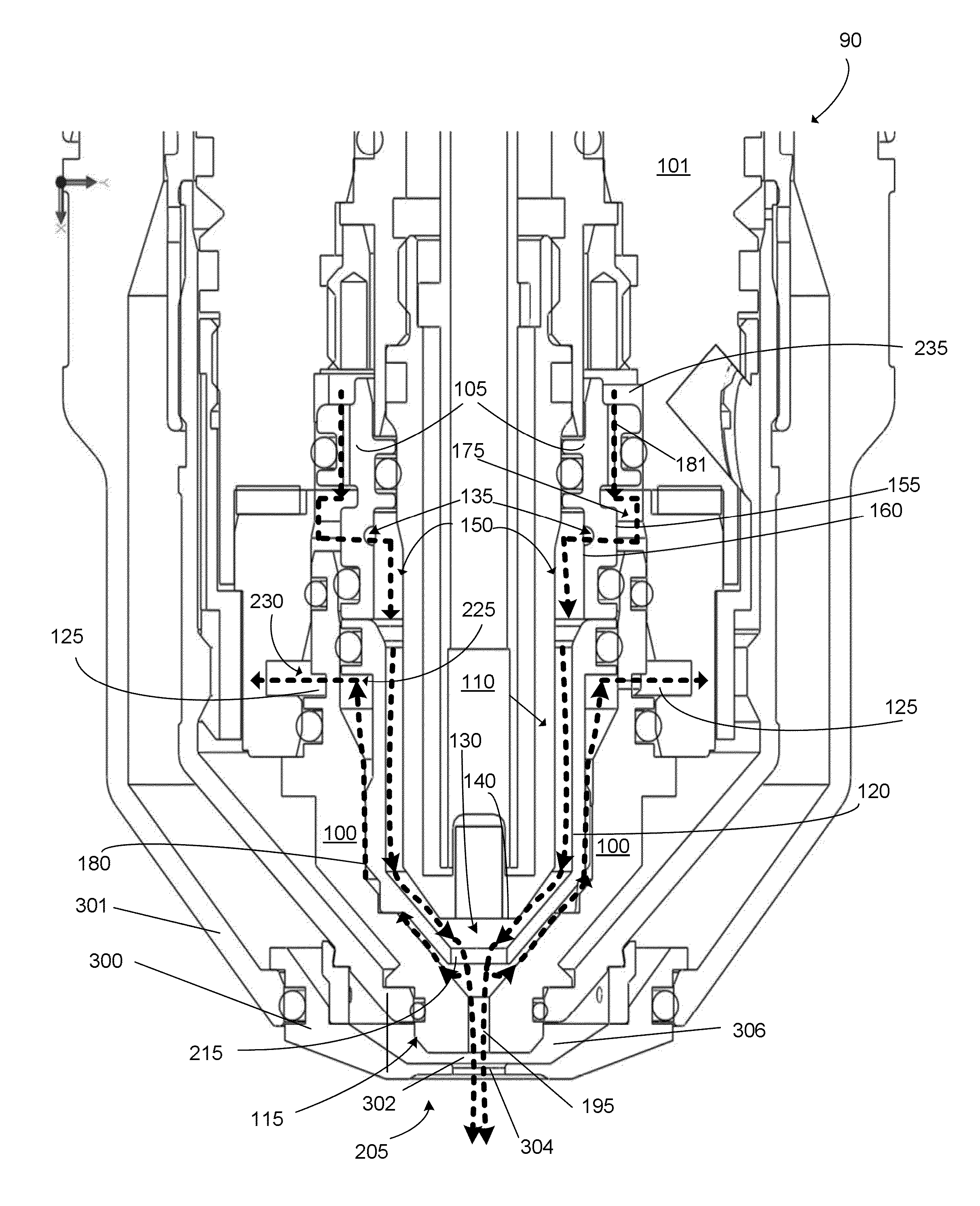
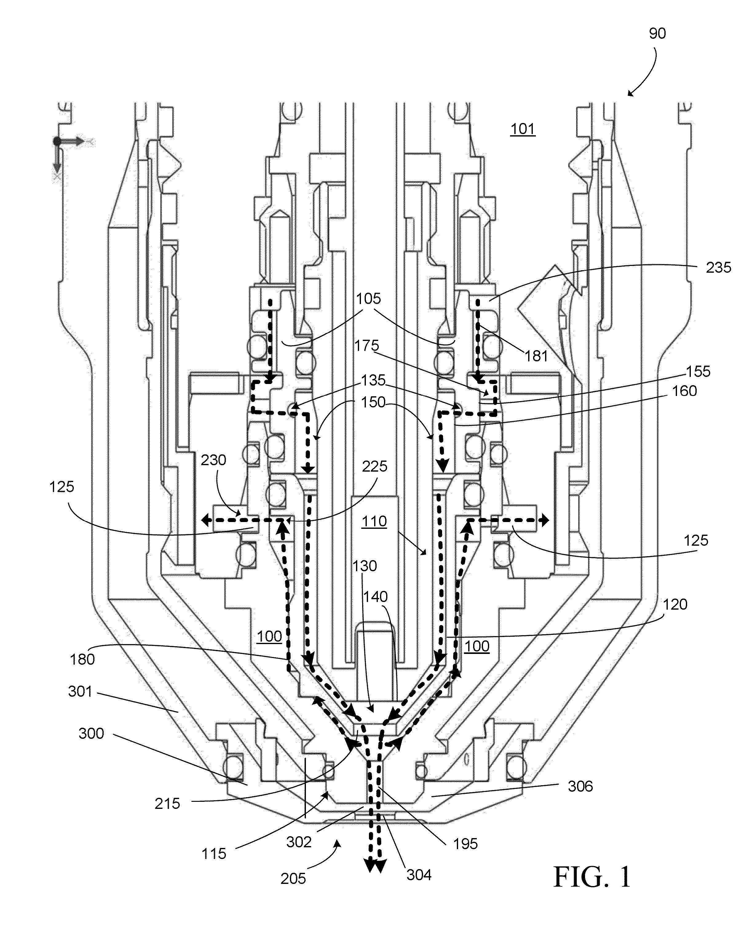
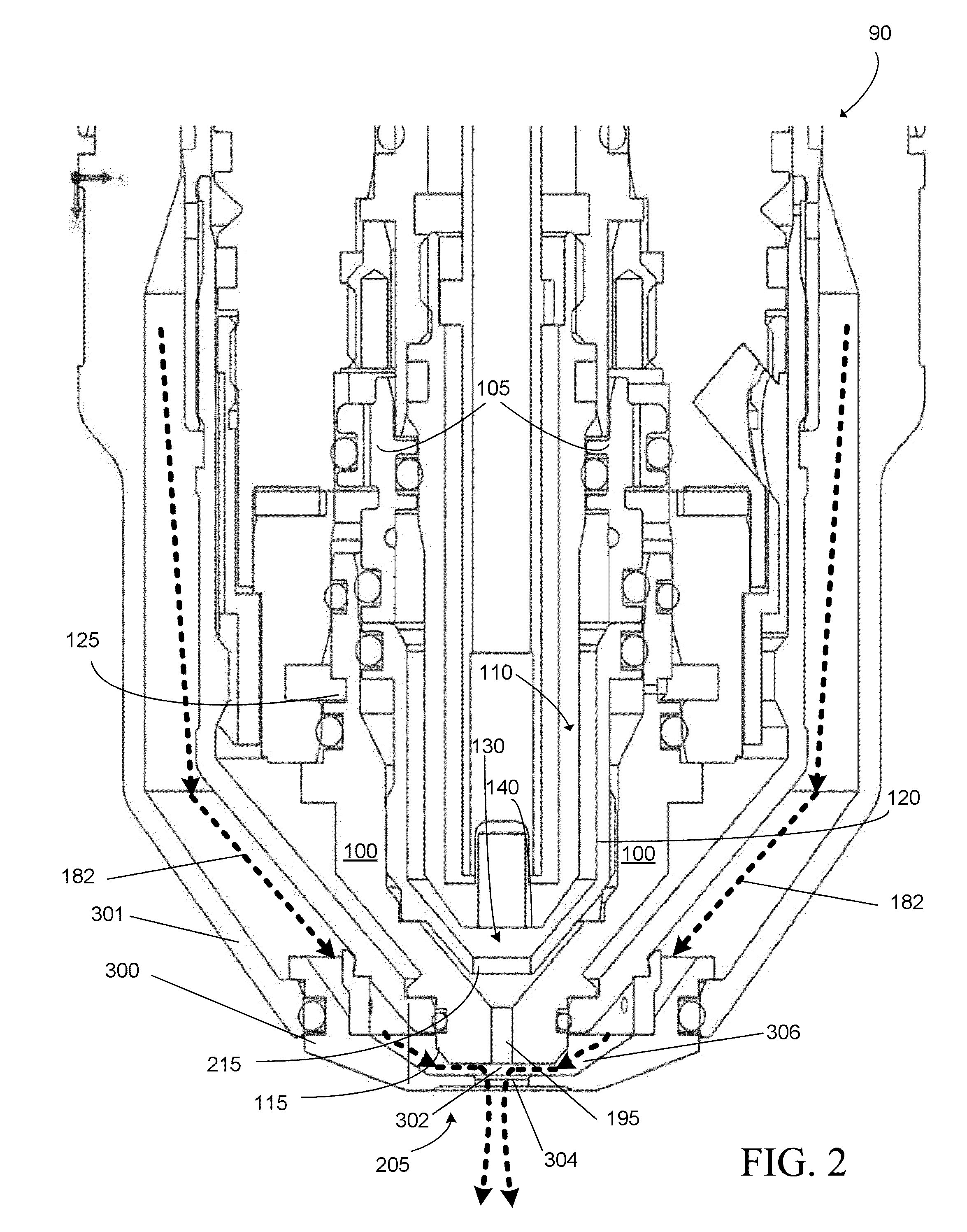
[0034]FIG. 1 shows an exemplary plasma arc torch, according to some embodiments of the present technology. A plasma arc torch can include a torch body 101 and a tip assembly 90 connected to the torch body 101. The tip assembly 90 can include a nozzle 100, a swirl ring 105, an electrode 110, and a plasma chamber 130. The torch defines a distal end 205, which is the end that is positioned closest to a workpiece (not shown) during torch operation. The electrode 110 has a distal end face 140 and an exterior surface 150. The plasma chamber 130 is defined, at least in part, by the distal end face 140 of the electrode 110 and the nozzle 100, which is situated in a spaced relationship from the electrode 110. The plasma chamber 130 is configured to receive a plasma gas.
[0035]The nozzle 100 includes a body 115, a liner 120 disposed within the body 115, and at least one plasma gas vent passage 125 formed in the body 115. The body 115 of the nozzle 100 can have a nozzle exit orifice 195 at the ...
PUM
| Property | Measurement | Unit |
|---|---|---|
| Pressure | aaaaa | aaaaa |
| Flow rate | aaaaa | aaaaa |
| Current | aaaaa | aaaaa |
Abstract
Description
Claims
Application Information