Eureka AIR delivers breakthrough ideas for toughest innovation challenges, trusted by R&D personnel around the world.

Medical instrument with sensor for use in a system and method for electromagnetic navigation

Inactive Publication Date: 2016-06-23
TYCO HEALTHCARE GRP LP
View PDF10 Cites 38 Cited by
  • Summary
  • Abstract
  • Description
  • Claims
  • Application Information

AI Technical Summary

Benefits of technology

The present patent describes a medical instrument that can identify its location in an electromagnetic field using a sensor. The instrument has a conductive material with a coil that is placed on the surface of the instrument and covered by a non-conductive material. The non-conductive material can be printed directly on the instrument or attached separately. The sensor is connected to a measurement device that senses an induced electrical signal based on a magnetic flux change. The location of the instrument in the electromagnetic field is identified based on the induced electrical signal. The patent also describes an electromagnetic navigation system that includes an EM board, a medical instrument, and a processor. The medical instrument has a sensor with a coil and a non-conductive material covering it, and the pair of contacts are connected to the coil. The system processor processes the induced electrical signal to identify the location of the instrument in the electromagnetic field.

Problems solved by technology

At this point, however, because the locatable guide with its sensor have been removed, the exact location of a distal end of the EWC, and by extension any instrument which might be passed there through is not precisely known.
Images generated by the non-invasive imaging technologies described above do not provide the resolution of live video imaging.
However, an endoscope is limited by its size and as a result cannot be navigated to the pleura boundaries of the lungs and other very narrow passageways as is possible with tools typically utilized in EMN.
As with the locatable guide, however, once the visualization instrument is removed the location of the distal end of the EWC is unclear.
Due to the small diameter of the EWC, simultaneous insertion of more than one instrument may be impractical.
Such repeated insertions and removals lengthen diagnostic or surgical time and efforts, and increase costs on patients correspondingly.

Method used


Image

  • Medical instrument with sensor for use in a system and method for electromagnetic navigation
  • Medical instrument with sensor for use in a system and method for electromagnetic navigation
  • Medical instrument with sensor for use in a system and method for electromagnetic navigation

Examples


Embodiment Construction

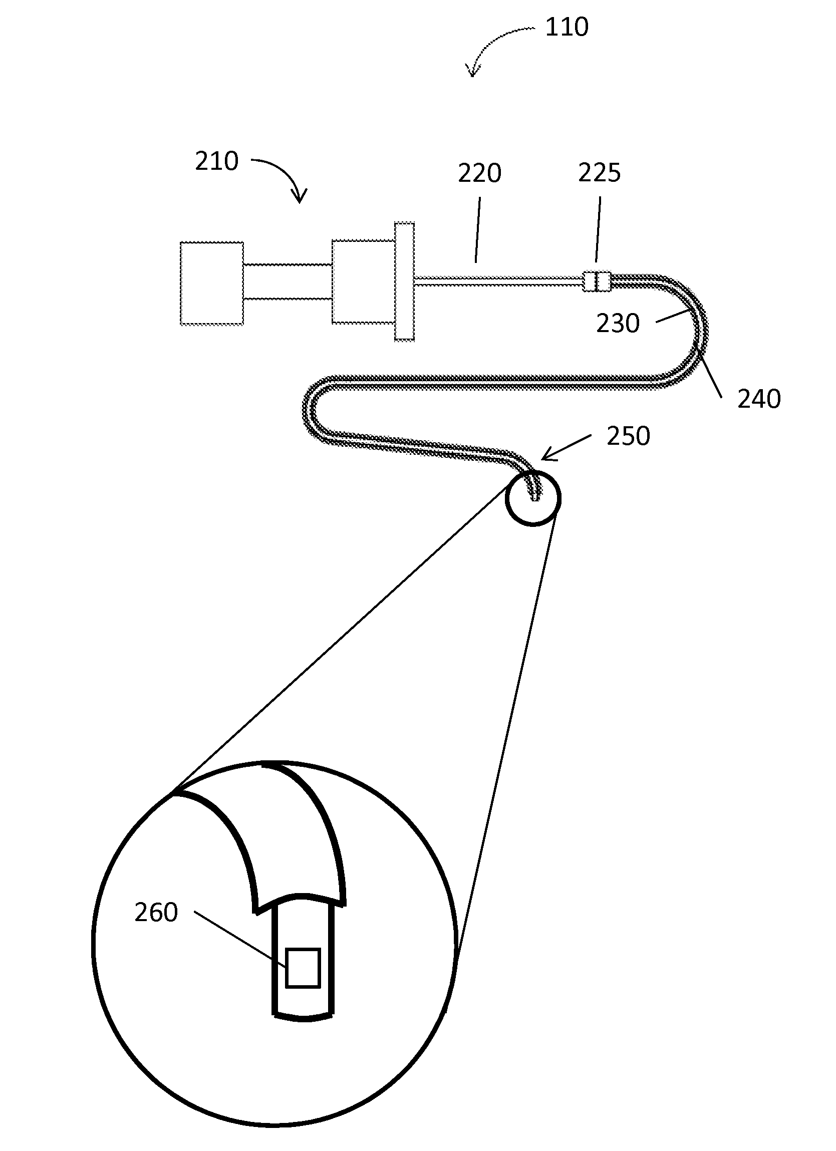
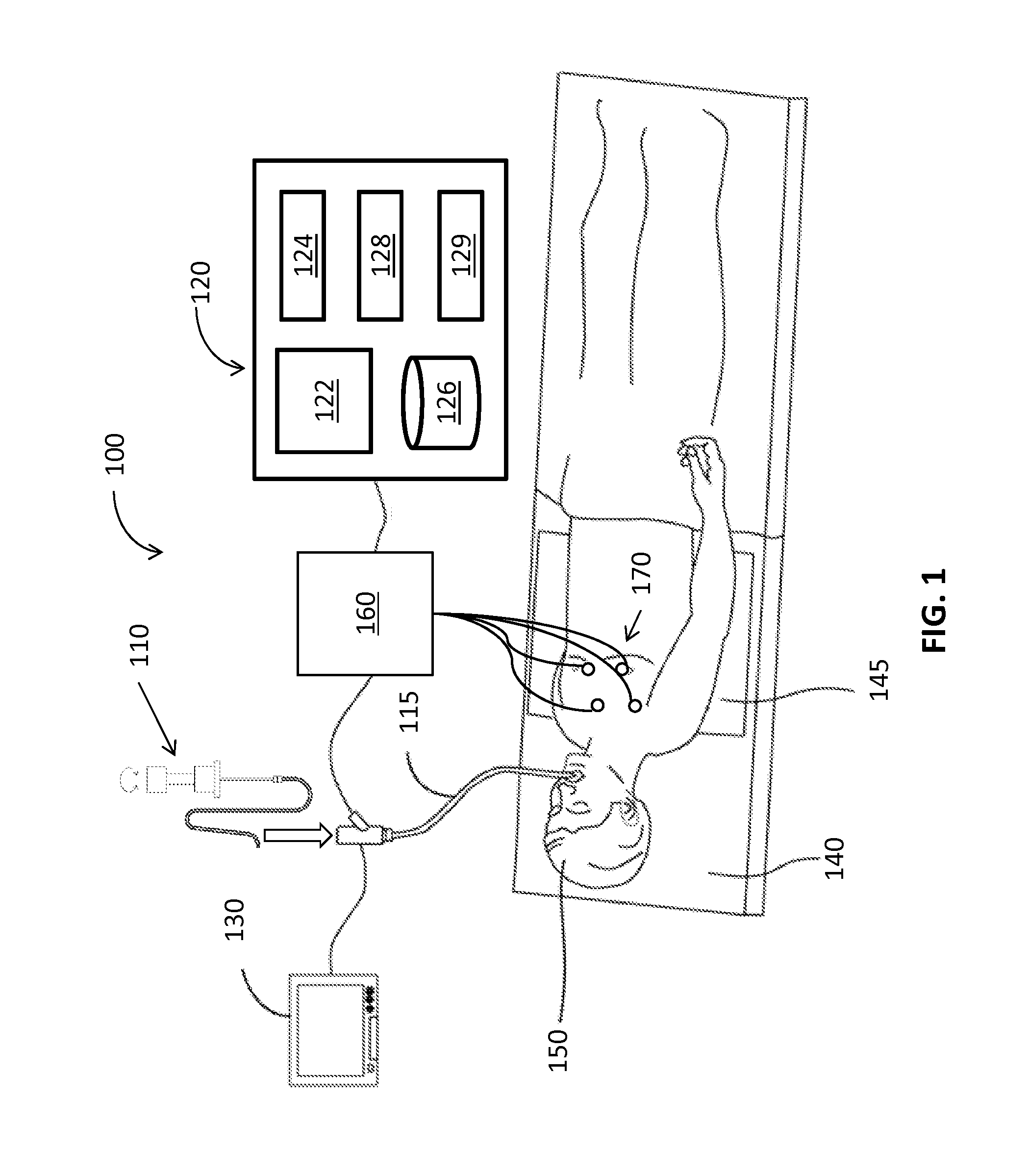
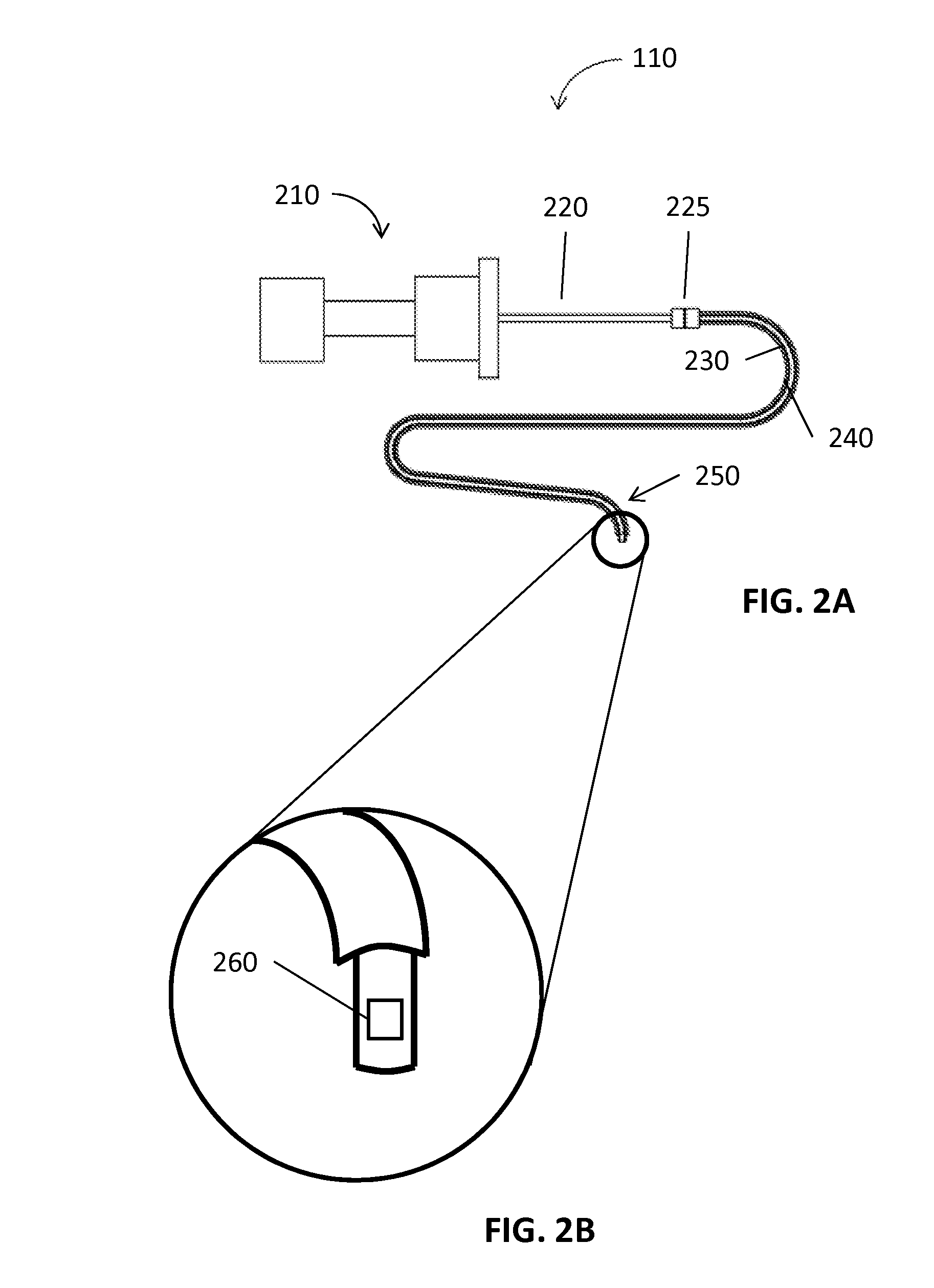
[0032]The present disclosure is related to medical instruments, systems and methods for identifying a location of medical instruments in an electromagnetic field by using a sensor. The sensors may be fabricated directly on or separately fabricated and then affixed to the medical instruments, including imaging instruments. One method of fabricating the sensors is via printing. Since the sensor may be inserted inside of patient's body with medical instruments, the location of the medical instruments is identified real-time. Further, the sensor may provide and trace an exact direction and location of the medical instrument with other imaging modality. Due to the small size of the sensor, medical instruments may incorporate the sensor inside or outside of the medical instruments, to facilitate continuous navigation. Although the present disclosure will be described in terms of specific illustrative embodiments, it will be readily apparent to those skilled in this art that various modifi...


PUM


Abstract

A medical instrument includes a sensor, a surface, at least one non-conductive material, and at least one pair of contacts. The sensor has at least one coil formed on a conductive material. The surface is suitable for receiving the sensor and can be placed in an EM field. The at least one non-conductive material covers the at least one coil of the sensor. The at least one pair of contacts are electrically connected to the at least one coil and connectable to a measurement device, which senses an induced electrical signal based on a magnetic flux change of the EM field. The location of the medical instrument in a coordinate system of the EM filed is identified based on the induced electrical signal in the sensor.

Description

CROSS REFERENCE TO RELATED APPLICATION[0001]The present application claims the benefit of and priority to U.S. Provisional Application Ser. No. 62 / 095,563, filed on Dec. 22, 2014, the entire contents of which are incorporated herein by reference.BACKGROUND[0002]1. Technical Field[0003]The present disclosure relates to a medical instrument including a sensor, and a system in which the location of the sensor can be detected and tracked. More particularly, the present disclosure relates to systems and methods that identify a location of a medical instrument having the sensor in an electromagnetic field.[0004]2. Discussion of Related Art[0005]Electromagnetic navigation (EMN) has helped expand the possibilities of treatment to internal organs and diagnosis of diseases. EMN relies on non-invasive imaging technologies, such as computed tomography (CT) scanning, magnetic resonance imaging (MRI), or fluoroscopic technologies. These images may be registered to a location of a patient within a...

Claims


Application Information

Patent Timeline
IPC IPC(8): A61B5/06
CPCA61B5/062A61B5/6852A61B2562/166
Inventor GREENBURG, BENJAMINPETERSON, ALEX A.SERDAR, DAVID J.COSTELLO, DAVID M.
Owner TYCO HEALTHCARE GRP LP
Why Eureka
Eureka Blog
Learn More