Muilti-functional power management system

a power management system and multifunctional technology, applied in the field of power conversion, can solve the problems of lack of integrated solutions, redundancy, cost, complexity, etc., and achieve the effect of reducing the number of power management systems, and increasing the complexity of the system

Active Publication Date: 2016-06-23
FLEX POWER CONTROL INC
View PDF35 Cites 74 Cited by
  • Summary
  • Abstract
  • Description
  • Claims
  • Application Information

AI Technical Summary

Benefits of technology

[0019]According to a third aspect of the design, there is provided a power management apparatus comprising a bi-directional AC-DC converter comprising a bidirectional boost converter coupled to an AC source, a high voltage DC link capacitor circuit coupled to the bidirectional boost converter and comprising at least one capacitor and a DC to DC converter circuit coupled to the high voltage DC link capacitor circuit and to a DC source. The bi-directional AC-DC converter is further coupled to at least one of AC and DC interface electric vehicle charging hardware.

Problems solved by technology

Implementing power conversion solutions in this manner results in designs requiring several components occupying a large amount of area or real estate, as well as complicated wiring schemes to integrate the several separate components in arrangements such as power utility grids, household loads, solar panel arrays, and fixed storage devices including batteries and the like.
In general, system designers have limited flexibility when choosing equipment for residential power applications and end up installing individual discrete systems supporting all of the electronics deployed, potentially including redundant components.
As a result, the lack of available integrated solutions add redundancy, complexity, and cost, and present physical space demands and heat issues for each conversion system installed.
Today, each of these functions requires separate hardware with commensurate expense and complexity.

Method used


Image

  • Muilti-functional power management system
  • Muilti-functional power management system
  • Muilti-functional power management system

Examples


Embodiment Construction

[0034]The following description and the drawings illustrate specific embodiments sufficiently to enable those skilled in the art to practice the system and method described. Other embodiments may incorporate structural, logical, process and other changes. Examples merely typify possible variations. Individual elements and functions are generally optional unless explicitly required, and the sequence of operations may vary. Portions and features of some embodiments may be included in, or substituted for, those of others.

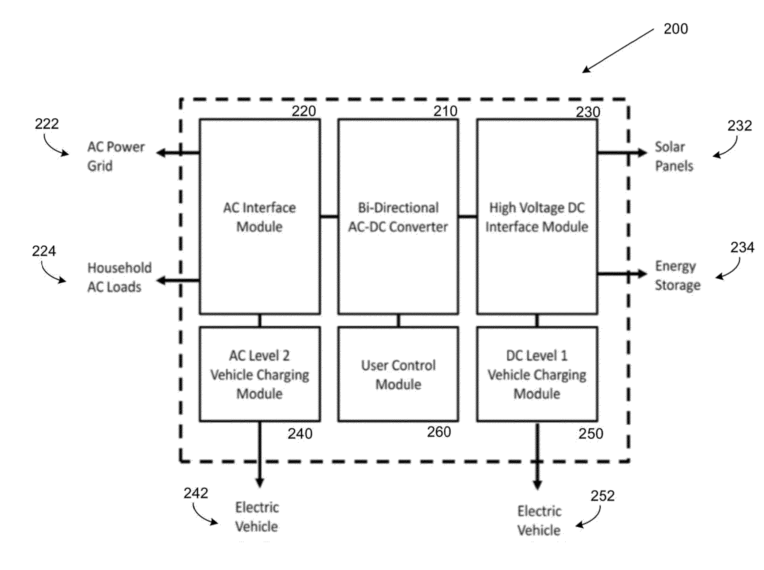
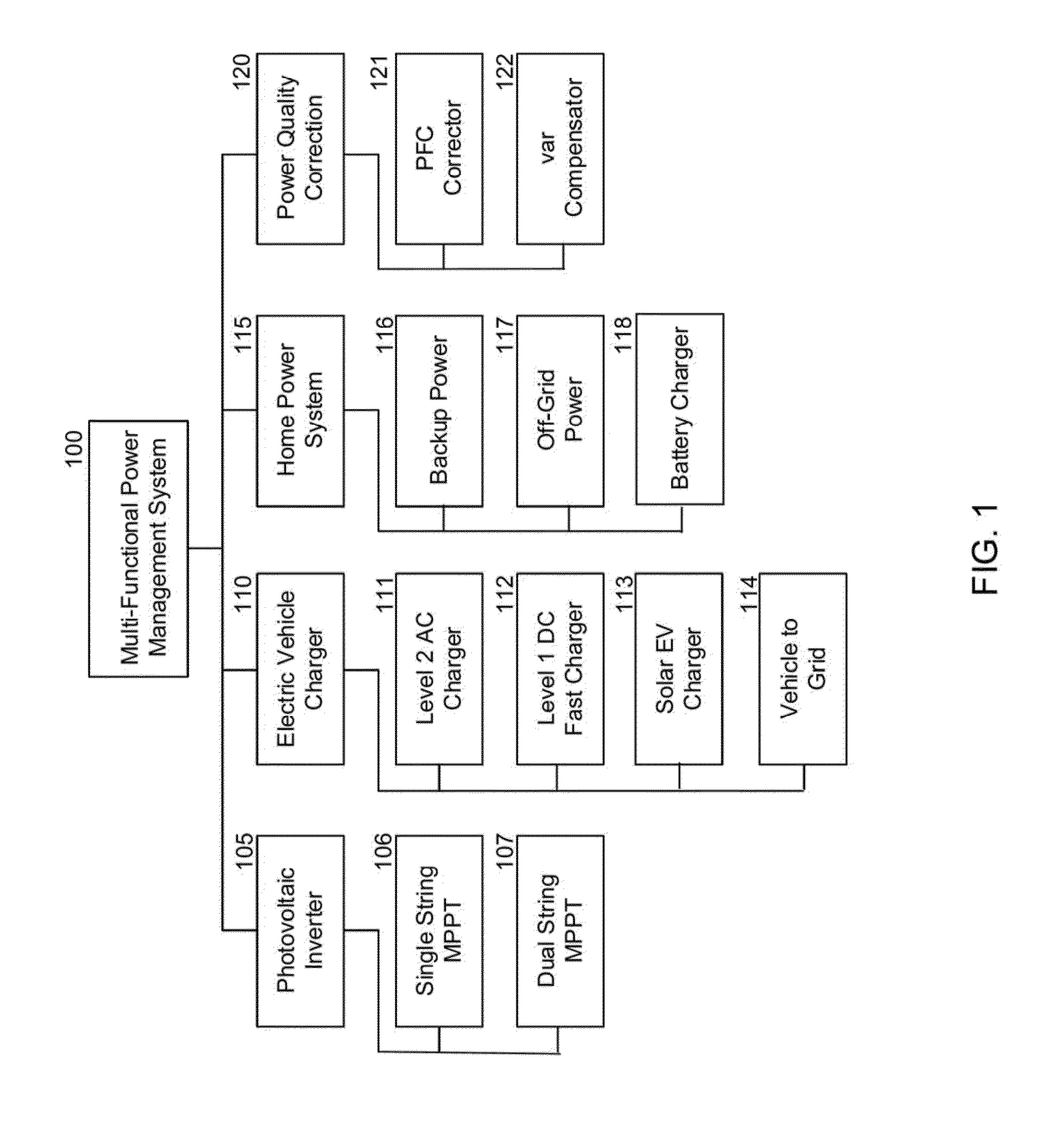
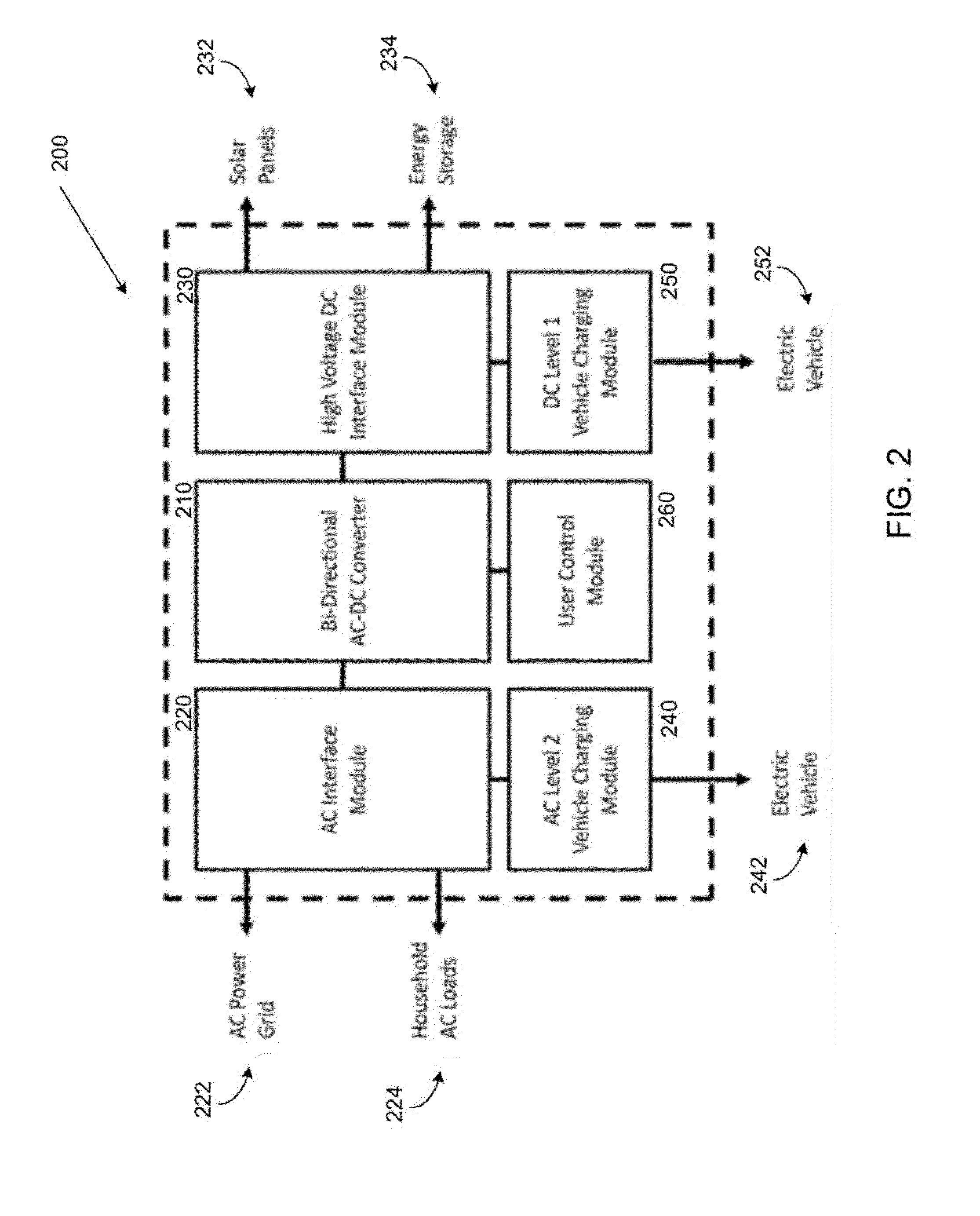
[0035]The present design is directed to a power converter and power management system configured to interoperate between and various AC and DC power sources and power sinks. The system leverages an integrated bi-directional power conversion apparatus for converting either AC power to DC power or DC power to AC power when the sources and sinks differ in a single modular electronic power management unit. The system monitors the power sources and sinks and switches each t...


PUM


Abstract

A power management apparatus is provided. The apparatus is configured to connect a plurality of DC power elements to a plurality of AC power elements and includes a DC interface module connected to the plurality of DC power elements, a bi-directional AC-DC converter connected to the DC interface module, and an AC interface module connected to the bi-directional AC-DC converter and the AC power elements.

Description

[0001]This application claims priority based on:[0002]U.S. Provisional Patent Application Ser. No. 62 / 095,204, inventors James Nagashima et al., entitled “Multi-Functional Power Management System,” filed Dec. 22, 2014;[0003]U.S. Provisional Patent Application Ser. No. 62 / 095,396, inventors James Nagashima et al., entitled “Highly Reliable AC-DC Power Converter with High Voltage DC Link,” filed Dec. 22, 2014, and[0004]U.S. Provisional Patent Application Ser. No. 62 / 095,432, inventors James Nagashima et al., entitled “Method to Reduce Losses in a High Voltage DC Link Converter,” filed Dec. 22, 2014, and the present application is being filed concurrently with:[0005]U.S. patent application Ser. No. ______, Attorney Docket FLPO0001, inventors James Nagashima et al., entitled “Reliable AC-DC Power Converter with High Voltage DC Link,” and[0006]U.S. patent application Ser. No. ______, Attorney Docket FLPO0002, inventors James Nagashima et al., entitled “Method to Reduce Losses in a High V...

Claims


Application Information

Patent Timeline
Patent Type & Authority Applications(United States)
IPC IPC(8): B60L11/18H02M7/68H02J3/38
CPCB60L11/1816H02M7/68H02J3/383Y02B70/3225Y04S20/222Y02T10/92Y02T90/14Y04S10/126B60L53/22B60L55/00B60L53/11B60L53/51B60L53/53H02J2310/14H02J2300/26H02J2300/24H02J3/381H02J3/14Y02E10/56Y02E60/00Y02T10/7072Y02T90/12Y02T10/70H02J3/322H02J2310/60H02J3/38H02M3/33584H02M7/219H02M7/5387
Inventor JAMES, NAGASHIMA MICHIOSMITH, GREGORY SCOTT
Owner FLEX POWER CONTROL INC
Why Eureka
Try Eureka