Vehicle lighting unit

a technology for vehicle lighting and lighting units, applied in fixed installations, lighting and heating devices, lighting support devices, etc., can solve the problems of reducing the utilization and affecting the efficiency of luminous flux utilization

Active Publication Date: 2016-06-23
STANLEY ELECTRIC CO LTD
View PDF4 Cites 16 Cited by
  • Summary
  • Abstract
  • Description
  • Claims
  • Application Information

AI Technical Summary

Benefits of technology

[0019]According to the above-mentioned aspect of the presently disclosed subject matter, even when the wavelength converting member is dislocated from the predetermined position due to some reasons, the laser light emitted from the laser light source and entering the lens memb

Problems solved by technology

In this vehicle headlight, there arises a problem in which the wavelength converting member is damaged, so that the laser light can erroneously exit through the damaged area to the outside.
In view of this, there further arises a problem in which the safety device cannot be properly applied to a lighting unit having a lens member that can control l

Method used


Image

  • Vehicle lighting unit
  • Vehicle lighting unit
  • Vehicle lighting unit

Examples


example 1

[0072]Under conditions in which the semiconductor laser element 22 had an output of 3 W, the lens member 40 had the prism 56 disposed in the region A2 illustrated in FIG. 10, and the light emitting device 20 did not have any wavelength converting member 26, the laser light rays Ray22 emitted from the semiconductor laser element 22 and exiting through the light exiting surface 48 were confirmed in terms of its output and resulting light distribution pattern.

[0073]The results showed that the output of the laser light rays Ray22 emitted from the semiconductor laser element 22 and exiting through the light exiting surface 48 was 0.11 W and the light distribution pattern shown in FIG. 11B was formed on a virtual vertical screen.

example 2

[0074]Under conditions in which the semiconductor laser element 22 had an output of 3 W, the lens member 40 had the prism 56 disposed in the region A1 illustrated in FIG. 9, and the light emitting device 20 did not have any wavelength converting member 26, the laser light rays Ray22 emitted from the semiconductor laser element 22 and exiting through the light exiting surface 48 were confirmed in terms of its output and resulting light distribution pattern.

[0075]The results showed that the output of the laser light rays Ray22 emitted from the semiconductor laser element 22 and exiting through the light exiting surface 48 was 0.02 W and the light distribution pattern shown in FIG. 11C was formed on a virtual vertical screen.

[0076]The test conditions and obtained results are listed in Table 1.

TABLE 1Prism(Location)Output (to 3 W)Light Distribution PatternExample 1A2 (FIG. 10)0.11 W (3.67%)FIG. 11BExample 2A1 (FIG. 9)0.02 W (0.67%)FIG. 11CComparativeNone2.75 W (91.7%)FIG. 11AExample 1

[0...

example 3

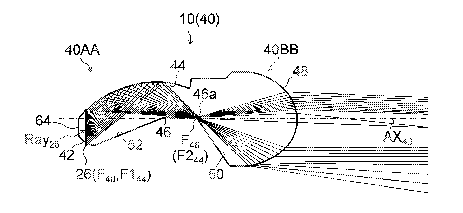
[0081]Under conditions in which the semiconductor laser element 22 had an output of 3 W, the lens member 40 had the prism 56 disposed in the region A1 illustrated in FIG. 9, and the light emitting device 20 had the wavelength converting member 26, the light rays Ray26 emitted from the wavelength converting member 26 and exiting through the light exiting surface 48 were confirmed in terms of its light flux and the maximum light intensity in the resulting low beam light distribution pattern.

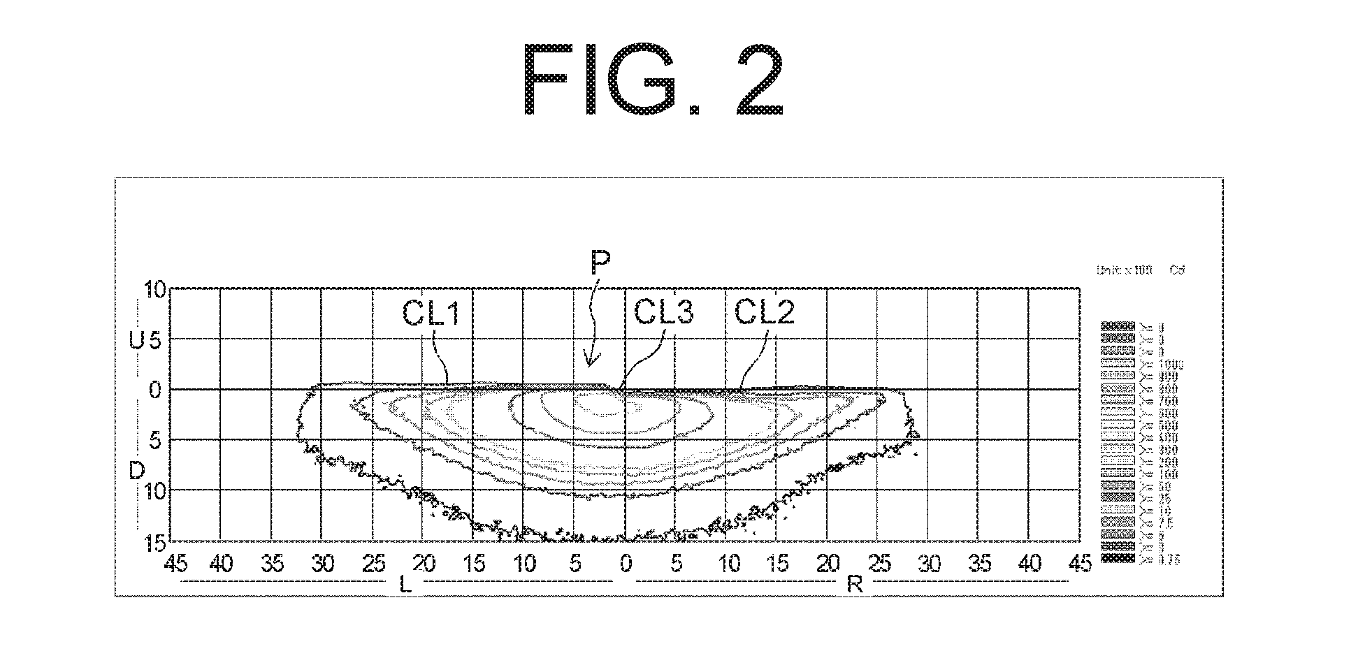
[0082]The results showed that the light flux of the light rays Ray26 emitted from the wavelength converting member 26 and exiting through the light exiting surface 48 was 254.8 lm and the maximum light intensity in the resulting low beam light distribution pattern was 13,150 cd. Further it was confirmed that the light flux utilization efficiency was 58.8% (when a not-illustrated outer lens was used).

TABLE 2Light FluxPrismMax LightUtilization(Location)Light Flux (lm)Intensity (cd)EfficiencyComparati...


PUM


Abstract

A vehicle lighting unit can prevent the erroneous emission of laser light from a lens member through its light emission surface to the outside even when a wavelength converting member is dislocated. The vehicle lighting unit can include a laser light source, the wavelength converting member configured to receive the laser light and wavelength-convert at least part of the laser light, and the lens member including a light incident surface on which light from the wavelength converting member or the laser light is incident, a first reflecting surface configured to totally reflect the light from the light incident surface, and a light exiting surface through which the light from the first reflecting surface can exit. The lens member can further include a total-reflection prevention structure at the first reflecting surface, configured to prevent the laser light entering the lens member from being totally reflected by the first reflecting surface.

Description

[0001]This application claims the priority benefit under 35 U.S.C. §119 of Japanese Patent Application No. 2014-259041 filed on Dec. 22, 2014, which is hereby incorporated in its entirety by reference.TECHNICAL FIELD[0002]The presently disclosed subject matter relates to a vehicle lighting unit provided with a lens member that can control light from a wavelength converting member, which can receive laser light for wavelength-converting the laser light.BACKGROUND ART[0003]There has been proposed a vehicle headlight including a laser light source and a wavelength converting member as well as a safety device, for example, those disclosed in Japanese Patent Application Laid-Open No. 2011-066069 (or US2011 / 0063115A1 corresponding to the Japanese laid-open publication). The vehicle headlight can project light obtained by wavelength-converting the original laser light from the laser light source by means of the wavelength converting member. In this vehicle headlight, there arises a problem...

Claims


Application Information

Patent Timeline
IPC IPC(8): F21S8/10B60Q1/08F21K99/00
CPCF21S48/1329F21S48/1145F21Y2101/025B60Q1/08F21K9/56B60Q1/0023F21Y2115/30F21S41/16F21S41/176F21S41/19F21S41/24F21S41/26F21S41/265F21S41/27F21S41/285F21S41/322F21S41/40F21S45/47F21S45/70F21S41/135
Inventor OWADA, RYOTARO
Owner STANLEY ELECTRIC CO LTD
Why Eureka
Try Eureka