Smart air duct cover
- Summary
- Abstract
- Description
- Claims
- Application Information
AI Technical Summary
Benefits of technology
Problems solved by technology
Method used
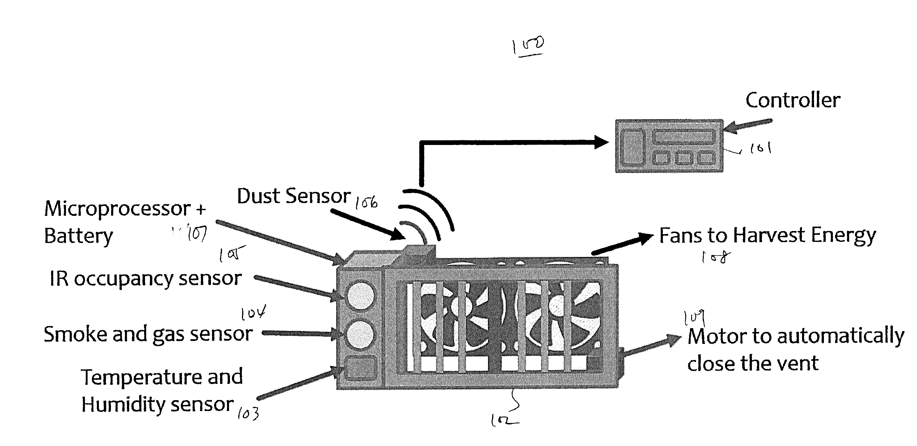
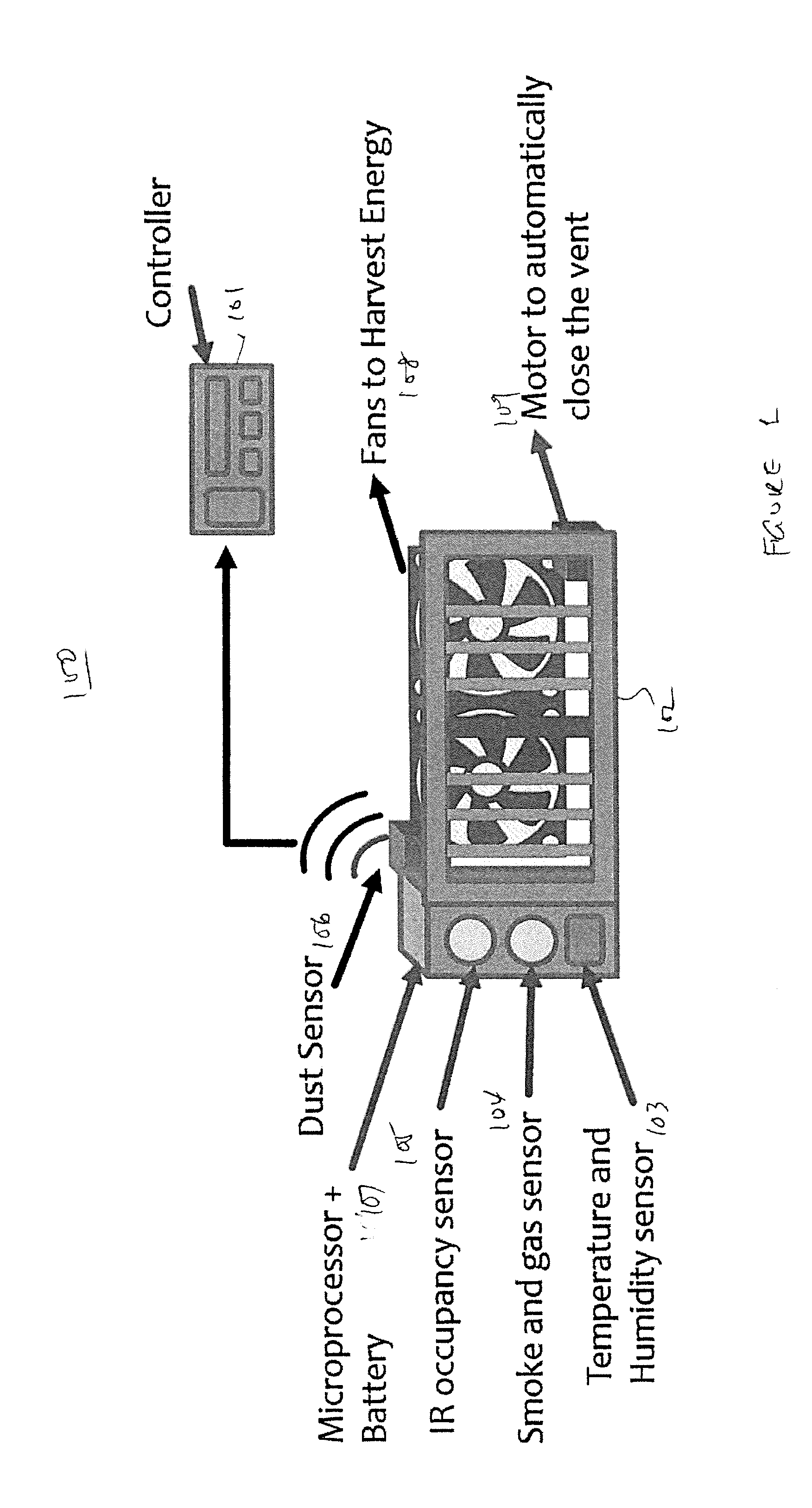
Image

Examples
Embodiment Construction
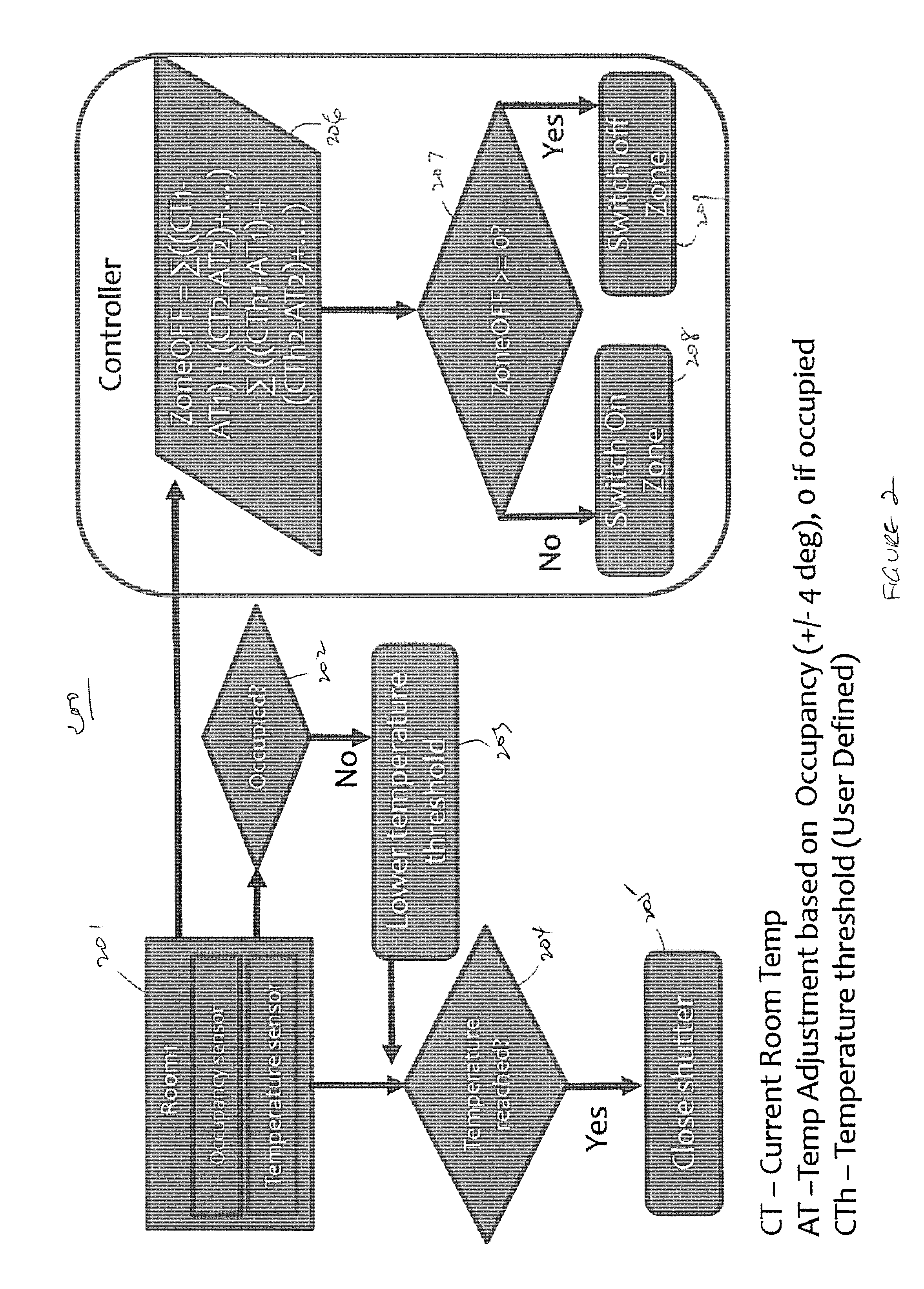
[0014]The inventor of the present invention observes that the living, dining and family rooms in a residence are unlikely to be occupied between certain hours at night, while bedrooms are likely occupied during those hours. However, in existing prior art systems, temperature is often set for the whole residence, so that even unoccupied areas are heated or cooled. Worse still, the thermostat in many residences is provided in a controller which is located in an area that is likely to be unoccupied during those times (e.g., the living room), and as the unoccupied areas usually are significantly different in floor area than the occupied areas (e.g., the bedrooms), the occupied rooms are over-heated or over-cooled. Because the whole residence is treated as a single zone, and because the sensors are often inappropriately placed, such an existing prior art system is not only inefficient, but also incapable of maintaining a comfortable temperature across the house, as to create discomfort i...
PUM
 Abstract
Description
Claims
Application Information