Radar device and signal processing method

a technology of radar device and signal processing method, which is applied in the direction of measurement device, using reradiation, instruments, etc., can solve the problems of not being able to accurately locate targets and the radar device may not calculate the appropriate correction value, and achieve the effect of high degree of accuracy

Inactive Publication Date: 2016-06-23
FUJITSU GENERAL LTD
View PDF1 Cites 19 Cited by
  • Summary
  • Abstract
  • Description
  • Claims
  • Application Information

AI Technical Summary

Benefits of technology

[0018][5] It may be the radar device according to [1], further including: a learning unit that learns a correction value for correcting information on the rotation angle, on the basis of information on the rotation angle detected by the first detecting unit, in which, in a case of learning the correction value, the control unit shortens the power supply stop periods of the receiving circuit.
[0021]According to any one of [1] to [7], even in a case where the internal temperature of the radar device is relatively low, the radar device can detect information on the rotation angle of the vehicle with a high degree of accuracy, and can derive the accurate locations of targets.

Problems solved by technology

Due to this change, the radar device may not calculate an appropriate correction value or may not derive the accurate locations of targets.

Method used


Image

  • Radar device and signal processing method
  • Radar device and signal processing method
  • Radar device and signal processing method

Examples


first embodiment

[0035]

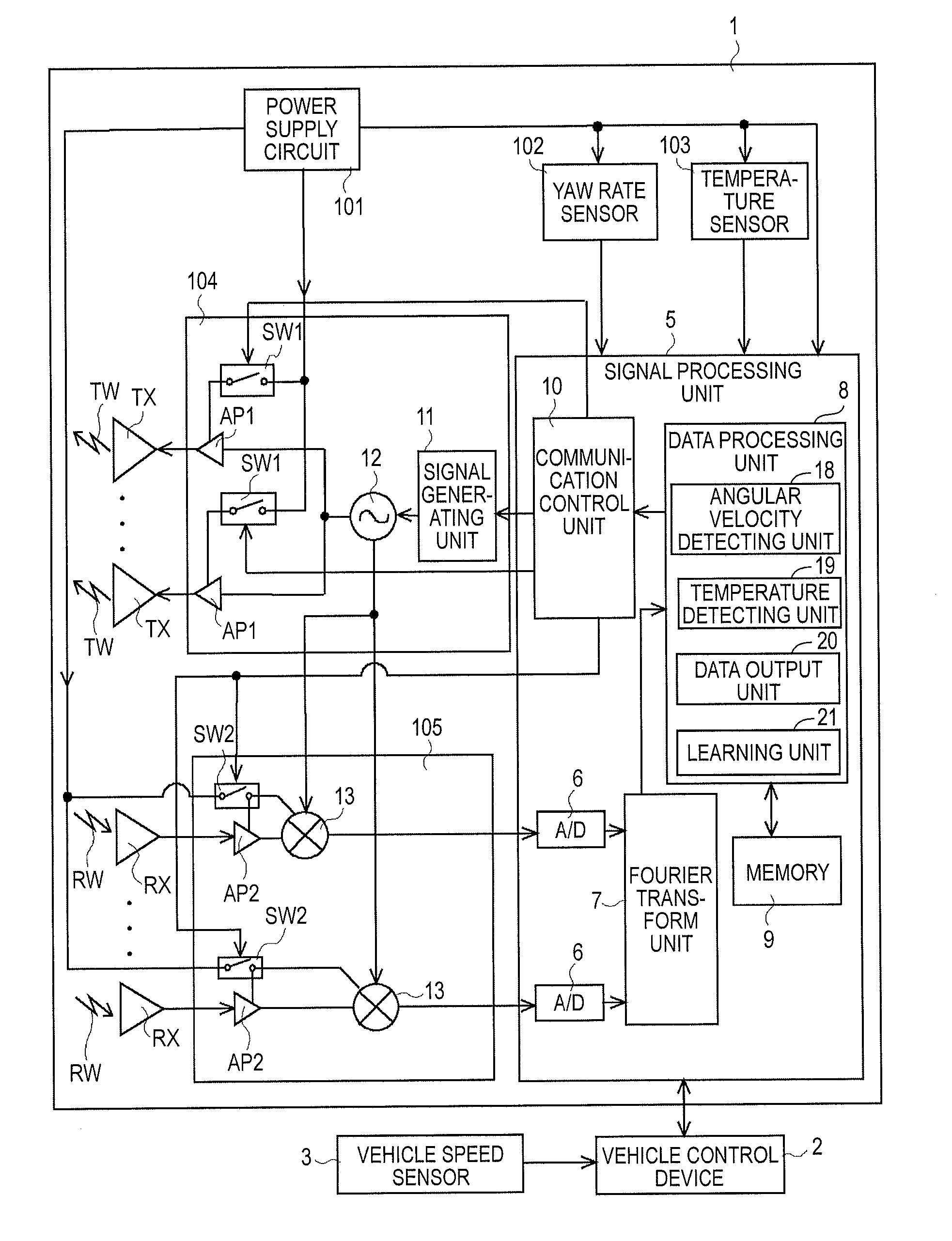
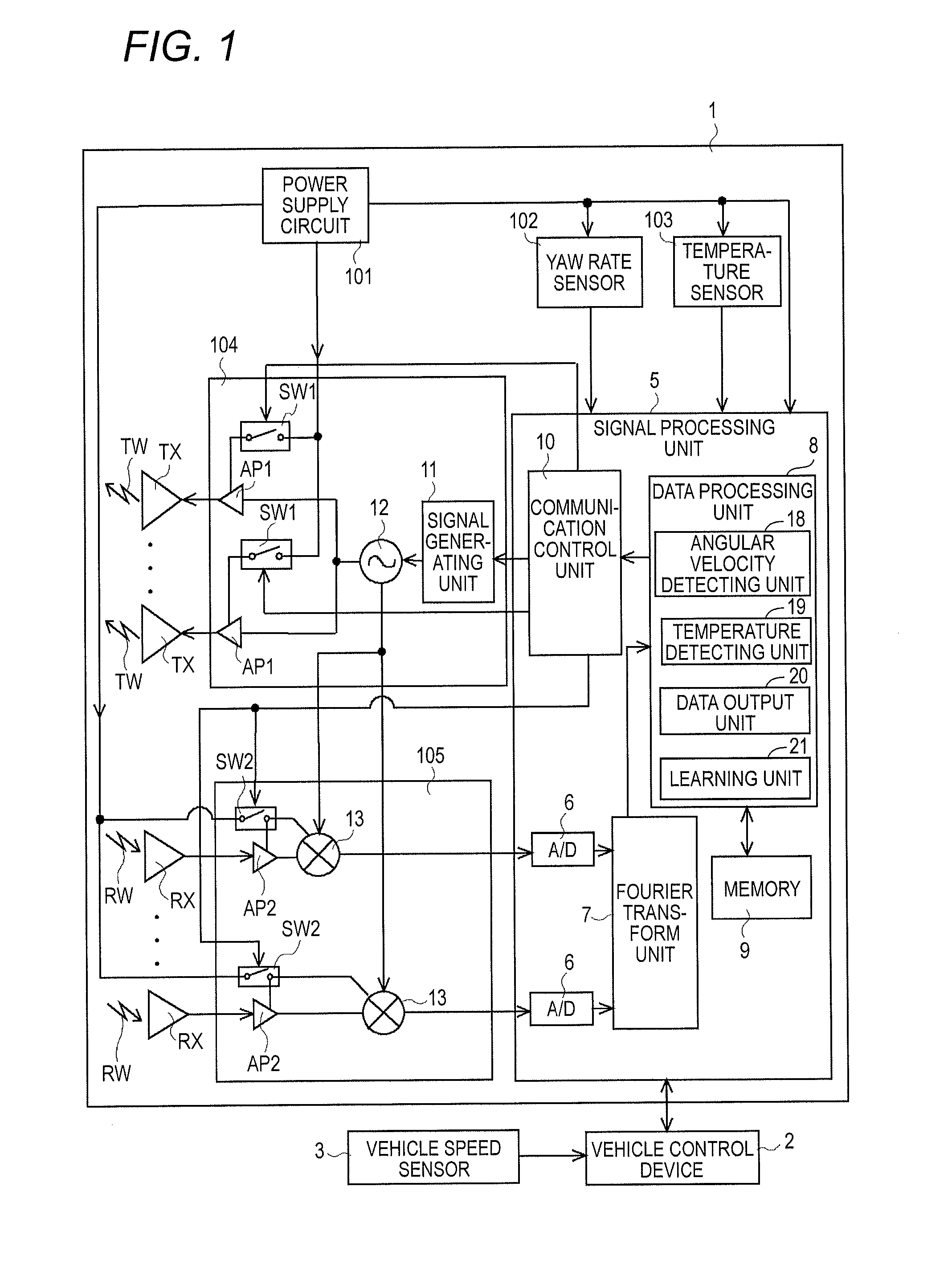
[0036]FIG. 1 is a view illustrating the configuration of a radar device 1. The radar device 1 is installed, for example, inside the front grille of a vehicle, and outputs transmission waves to the outside of the vehicle, thereby receiving reflected waves from targets. The radar device 1 derives targets existing around the vehicle, for example, by frequency-modulated continuous waves (FM-CWs).

[0037]Also, the radar device 1 is electrically connected to a vehicle control device 2. The vehicle control device 2 is connected to some components of the vehicle such as a brake and a throttle, and acquires target information items output from the radar device 1, and controls behavior of the vehicle.

[0038]Further, the vehicle control device 2 is electrically connected to a vehicle speed sensor 3. On the basis of the number of revolutions of the axle of the vehicle, the vehicle speed sensor 3 outputs a signal according to the speed of the vehicle, to the vehicle control device 2. The vehi...

second embodiment

[0107]Now, a second embodiment will be described. In a case where the internal temperature of the radar device is equal to or lower than the predetermined temperature, a transmission / reception control unit 10 of the second embodiment performs control such that the switches SW1 of the transmission IC 104 are almost always on.

[0108]The configuration and process of a radar device 1 of the second embodiment are almost the same as those of the first embodiment, except a portion of the content of control on the switches SW1 described above. Hereinafter, the difference will be mainly described with reference to FIG. 11.

[0109]FIG. 11 is a time chart illustrating timings to switching on or off the switches SW1 and SW2 of the second embodiment.

[0110]In the first embodiment described above, as described with reference to FIG. 8, in the case where the first period T1 has elapsed, the transmission / reception control unit 10 outputs a control signal for switching off the switches SW1, to the switc...


PUM


Abstract

A radar device includes: a receiving circuit mixing a transmission signal with reception signals; a first detecting unit detecting information on the rotation angle of a vehicle equipped with the radar device, on the basis of an output signal of a yaw rate sensor; a second detecting unit detecting the internal temperature of the radar device on the basis of an output signal from a temperature sensor; a power supply circuit supplying electric power to the receiving circuit and the yaw rate sensor; and a control unit repeatedly setting power supply periods and power supply stop periods of the receiving circuit, in which, in a case where the internal temperature is equal to or lower than a predetermined temperature, the control unit performs control such that the power supply stop periods of the receiving circuit become shorter than those in a case where the internal temperature exceeds the predetermined temperature.

Description

CROSS-REFERENCE TO RELATED APPLICATIONS[0001]This application is based on and claims priority under 35 USC 119 from Japanese Patent Application No. 2014-257182 filed on Dec. 19, 2014, the entire content of which is incorporated herein by reference.BACKGROUND[0002]1. Technical Field[0003]The present invention relates to transmission / reception control of a radar device.[0004]2. Related Art[0005]In general, a radar device outputs a transmission wave to the outside of the radar device, and receives reflected waves of the transmission wave from targets, and derives target information items such as the locations of the targets, on the basis of reception signals corresponding to the reflected waves.[0006]In the case where the radar device performs a target information deriving process as described above, a power supply circuit supplies electric power to individual internal devices of the radar device. For example, the power supply circuit supplies electric power to individual devices such ...

Claims


Application Information

Patent Timeline
Patent Type & Authority Applications(United States)
IPC IPC(8): G01S7/35G01S13/86G01S13/58
CPCG01S7/35G01S13/86G01S13/58G01S7/352G01S7/40G01S7/4004G01S13/931G01S2013/932G01S2013/9322
Inventor OKA, KENJIMATSUSHITA, TAKASHIGOTO, KUNIHIRONIIRO, HIDEAKI
Owner FUJITSU GENERAL LTD
Why Eureka
Try Eureka