Supercharge Your Innovation With Domain-Expert AI Agents!

Fiducial-based correlative microscopy

a correlative microscopy and optical microscope technology, applied in the field of correlative light and electron microscopy imaging, can solve the problems of limited correlation of ipalm and electron microscopy (em) images, limited resolution of images collected with conventional optical microscopes, and limited diffraction of conventional optical microscopes, etc., to achieve accurate correlation

Active Publication Date: 2016-06-23
FEI CO
View PDF0 Cites 1 Cited by
  • Summary
  • Abstract
  • Description
  • Claims
  • Application Information

AI Technical Summary

Benefits of technology

[0014]The foregoing has outlined rather broadly the features and technical advantages of the present invention in order that the detailed description of the invention that follows may be better understood. Additional features and advantages of the invention will be described hereinafter. It should be appreciated by those skilled in the art that the conception and specific embodiments disclosed may be readily utilized as a basis for modifying or designing other structures for carrying out the same purposes of the present invention. It should also be realized by those skilled in the art that such equivalent constructions do not depart from the scope of the invention as set forth in the appended claims.

Problems solved by technology

Images collected with a conventional optical microscope are limited in resolution to about half of the wavelength of the light used.
Because of this limitation, conventional optical microscopes are said to be diffraction limited.
Correlation of iPALM and electron microscopy (EM) images, however, is limited.
This allows accurate location information in the X-Y plane, but poor localization in the Z-plane.
This becomes problematic because the sample section can undergo changes due to electron and ion beam-induced distortion as well as changes that can occur in the sample due to sample preparation and insertion into vacuum for charged particle processing.
However, such attempts do not overcome the deficiencies in data correlation due to deformation of the sample.
Another difficulty presented by current methods of using fluorescent markers is the presence of fluorescent dye throughout the sample volume containing the markers.
As a result, the brightness of a dye dispersed throughout the sample volume may produce so much fluorescence that it is difficult to accurately locate nearby areas of interest.

Method used


Image

  • Fiducial-based correlative microscopy
  • Fiducial-based correlative microscopy
  • Fiducial-based correlative microscopy

Examples


Embodiment Construction

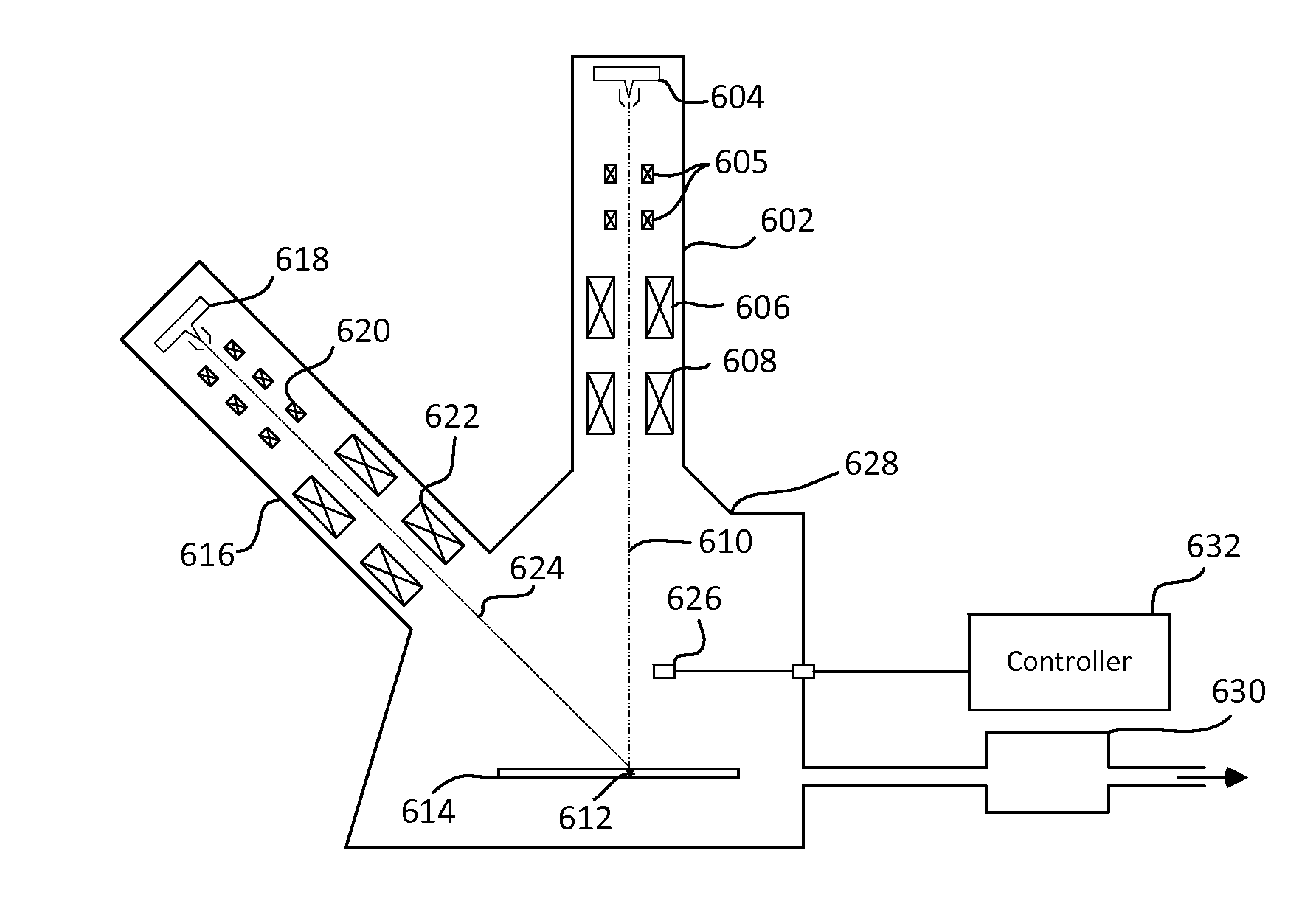
[0025]The methods described herein produce three-dimensional images of a sample with more accurate correlation data between optical microscopy and electron microscopy. The methods are not limited to any particular optical microscopy technique or to any particular charged particle beam imaging technique. The invention can be used with diffraction limited optical techniques and super-resolution optical techniques. Embodiments can also be used with both broad field optical techniques, such as PALM, iPALM, STORM, SIM, STED, structured illumination techniques, and 4Pi, as well as scanning techniques, such as scanning confocal microscopy, near field scanning optical microscopy, and TIRF. The invention can be used with deterministic super-resolution techniques, such as STED, GSD, RESOLFT and SSIM, as well as stochastic super-resolution techniques, such as SOFI and all single-molecule localization methods (SMLM) such as SPDM, SPDMphymod, PALM, FPALM, STORM and dSTORM. These techniques are l...


PUM

PropertyMeasurementUnit
volumeaaaaaaaaaa
opticalaaaaaaaaaa
optical systemaaaaaaaaaa

Abstract

A method is provided for preparing a sample for correlative optical and electron imaging and correcting aberrations in the imaging process due to sample deformation. Dye-coated fiducial markers are distributed throughout the sample volume. The fiducial markers are preferably in the form of polystyrene nanospheres that are functionalized on their surface and subsequently treated with a fluorescent dye. The dye does not penetrate the sphere but only binds to the surface. By limiting the dye to the surface of the nanospheres, the shape of the spheres can be determined in iPALM and in charged particle images aiding in tracking of physical changes that may occur to the sample volume.

Description

TECHNICAL FIELD OF THE INVENTION[0001]The present invention relates to correlative microscopy and in particular to correlative light and electron microscopy imaging.BACKGROUND OF THE INVENTION[0002]Microscopic images of cellular structure in biological samples can reveal important information regarding biological processes and cellular architecture. A correlative approach, which uses both optical microscopy and electron microscopy, produces the most comprehensive results. For example, light microscopy information can be used to identify areas of biological importance and their dynamics within a sample. Then electron microscopy can be used to resolve structural details within those areas after fixation and / or staining.[0003]Images collected with a conventional optical microscope are limited in resolution to about half of the wavelength of the light used. For practical optical microscopy this limit is around 200 nm. Because of this limitation, conventional optical microscopes are said...

Claims


Application Information

Patent Timeline
Patent Type & Authority Applications(United States)
IPC IPC(8): H01J37/22H01J37/26G01N21/64
CPCH01J37/222G01N21/6486H01J2237/26H01J37/26G01N2021/6439G01N21/6428G01N23/223G01N21/6458G02B21/365G02B21/0032G01N21/6456G02B21/0076G02B21/008G02B21/16H01J2237/221H01J2237/24578H01J2237/2611
Inventor RANDOLPH, STEVENMIYASAKI, JAMESSTRAW, MARCUS
Owner FEI CO
Features
  • R&D
  • Intellectual Property
  • Life Sciences
  • Materials
  • Tech Scout
  • Unparalleled Data Quality
  • Higher Quality Content
  • 60% Fewer Hallucinations
Learn More