
Probe Routing in a Network

Inactive Publication Date: 2016-06-23
KONINK KPN NV +1
View PDF7 Cites 3 Cited by
  • Summary
  • Abstract
  • Description
  • Claims
  • Application Information

AI Technical Summary

Benefits of technology

The invention describes a method for probing a network by sending a probe packet through a route in the network. This method allows the probe packet to be sent over a route that is managed at a node in the network, reducing delays caused by processing at the nodes. The method also allows for the probing of routes and links that might not be possible with other methods. The method can be used in an IP network by changing the routing rules at a node and ensuring packet forwarding. The technical effects of this invention include improved efficiency and accuracy in probing networks and the ability to probe routes and links that might be previously inaccessible.

Problems solved by technology

Information revealed by probing is typically limited by the method used.
For example in a home or domestic network an operator can install probing software on the home gateway and perhaps a proprietary TV set top box, but an operator cannot necessarily install probing software on the user's own PC or game box, XBOX or other similar device.
Therefore even though the operator may be supplying a gateway device through which the network communicates with the wider internet, the operator may not be able to derive accurate information about devices on the network which pose difficulties or otherwise affect the network.
However this method cannot be used to measure all links, typically due to probing limitations as mentioned earlier.
These known solutions are not applicable to all networks and in particular they are less applicable to a network typically found in a home or domestic situation.
The TTL-based approach is not applicable because a typical home network has many layer 2, e.g. Ethernet, hops, but no layer 3, e.g. IP, hops.
Thus, since a switch will not subtract 1 from the TTL value and will not sent ICMP ‘TTL exceeded’ messages, the TTL approach is typically meaningless in a home network.
Also, the cross-correlation method is not useful because the home network is typically a tree topology whereas the cross-correlation probing method requires different routes to go through the link being investigated.
The packet processing which occurs at any node introduces an unknown time delay and therefore the results of the probing method are inaccurate.
Additionally, the probe method using IP encapsulation suffers a further inaccuracy because as the IP data packets are unrolled at each node to strip out the top IP header for transfer into the header of the new outgoing packet, the size of the overall IP packet reduces and this produces an inaccuracy because while network probing results are based on packet size, this method results in a variable packet size over the entire route.
It is a problem to accurately probe a network.

Method used


Image

  • Probe Routing in a Network
  • Probe Routing in a Network
  • Probe Routing in a Network

Examples


Embodiment Construction

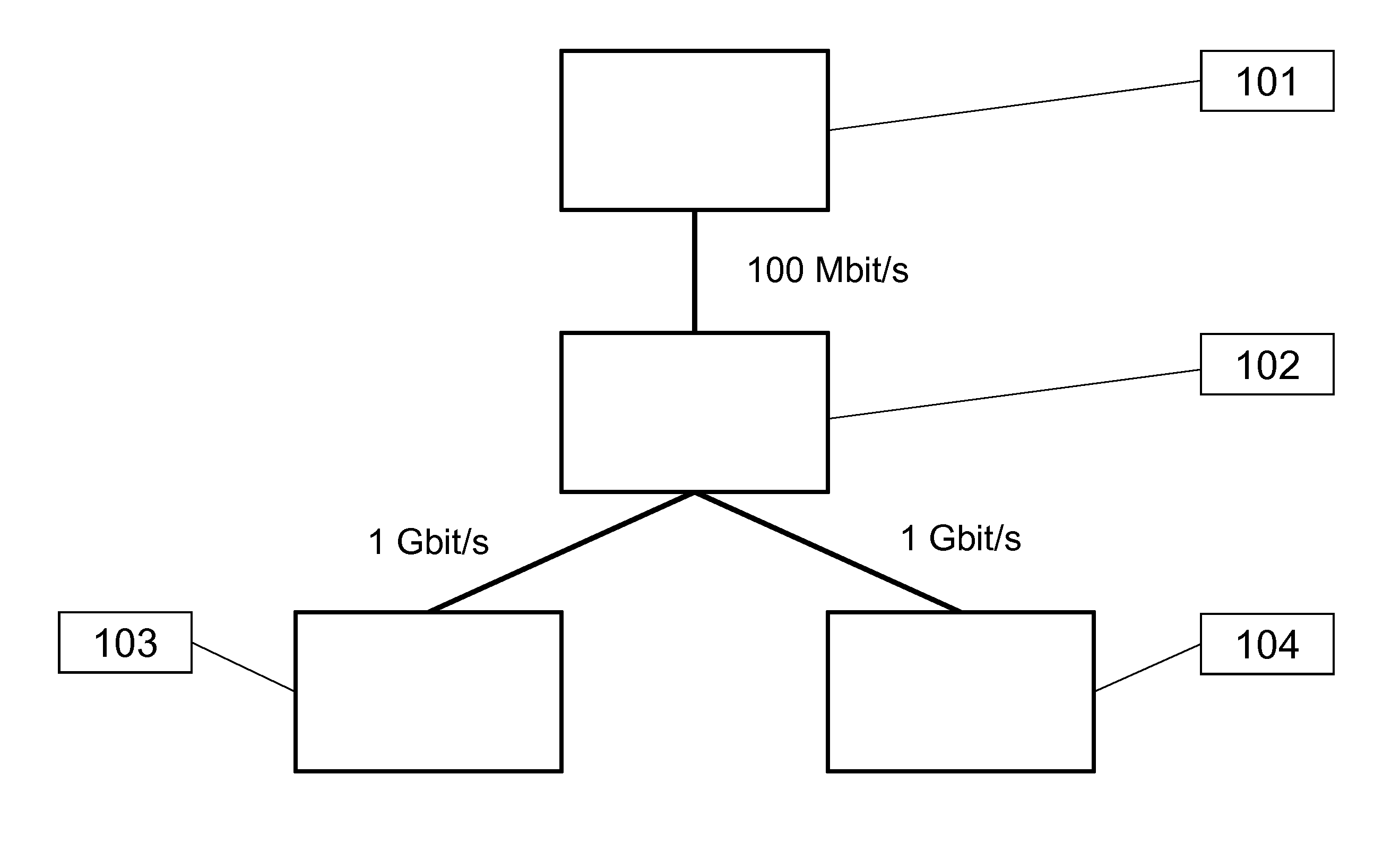
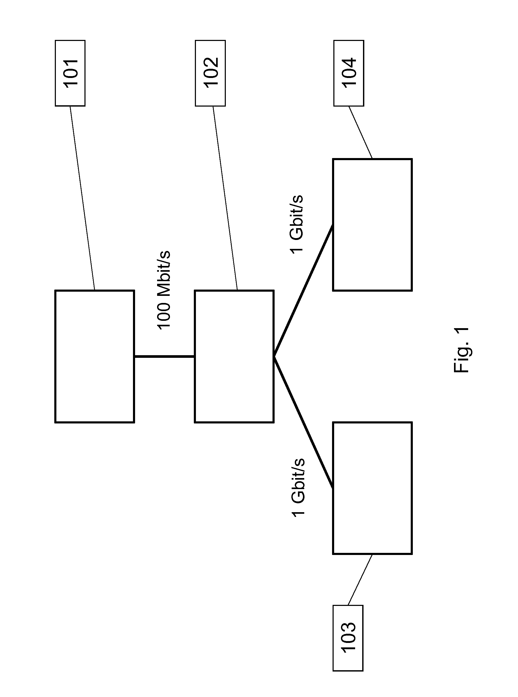
[0036]FIG. 1 shows a problem in network probing which is solved by the invention. The problem is that of how to probe a specific network route or a part of a specific route, sometimes known as a ‘hop’, when the entity performing the probing does not have access to any of the devices on that route. In this sense the lack of access means not being able to install probing and / or monitoring software on all the devices or on specific relevant devices on that route. The lack of access means the entity has no way of probing the specific route, let alone a hop on the route.

[0037]A very simple, and typical, network configuration is shown in which a home gateway 101 is connected to a switch 102 which is itself connected to two devices 103 and 104. Device A, 103, and device B, 104, are both end devices in this particular network. The switch 102 could also be any other network node for example a router, a wireless router, etc. The home gateway 101 is a boundary device on the edge of the network...


PUM


Abstract

A method of network probing is described suitable for probing between a probe node and a destination node. The network comprises a further node which is connected to the probe node and the destination node. A node is typically selected to be a redirecting node and the routing rules at this redirecting node are changed. A node is typically selected to be a forwarding node and packet forwarding is enabled at the forwarding node. A probe packet transmitted between the probe node and the destination node can travel via the forwarding node. The result improves network probing by allowing probing of links not otherwise available for probing from the probe node, but without the disadvantages of complex packet processing at each node in the probe pathway.

Description

[0001]The invention concerns a method of probing a network between a probe node and a destination node, wherein the network comprises a further node and further comprises a connection between the probe node and the destination node, a connection between the probe node and the further node and a connection between the further node and the destination node. The method also relates to a network.BACKGROUND TO THE INVENTION[0002]Probing a network is typically performed to identify or quantify facts about the network, for example available bandwidth and capacity in parts of the network, network topology and other network characteristics such as whether ports are open or closed or whether certain functions are enabled at nodes within the network.[0003]Network probing can be performed both actively and passively. In active probing an element connected to the network actively sends out probe packets on the network, and another element in the network receives these probes. Sometimes probes ar...

Claims


Application Information

Patent Timeline
IPC IPC(8): H04L12/741H04L12/26H04L45/74
CPCH04L43/12H04L45/74H04L41/04H04L43/10H04L45/304H04L45/66H04L45/70H04L41/344
Inventor STOKKING, HENSDEN HARTOG, FRANKHERRERA VAN DER NOOD, MANUEL
Owner KONINK KPN NV
Learn More