

Printing apparatus, printed matter and method of manufacturing printed matter
- Summary
- Abstract
- Description
- Claims
- Application Information
AI Technical Summary
Benefits of technology
Problems solved by technology
Method used
Image

Examples
first embodiment
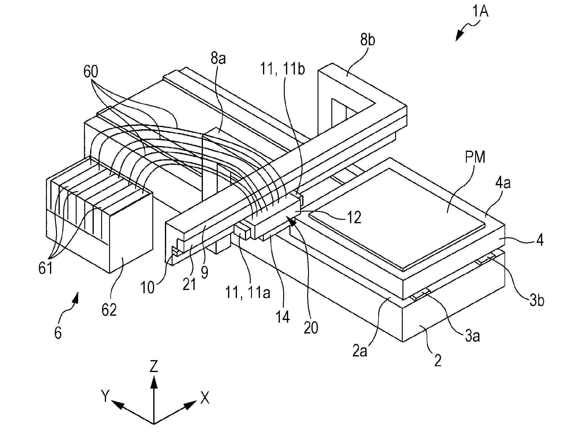
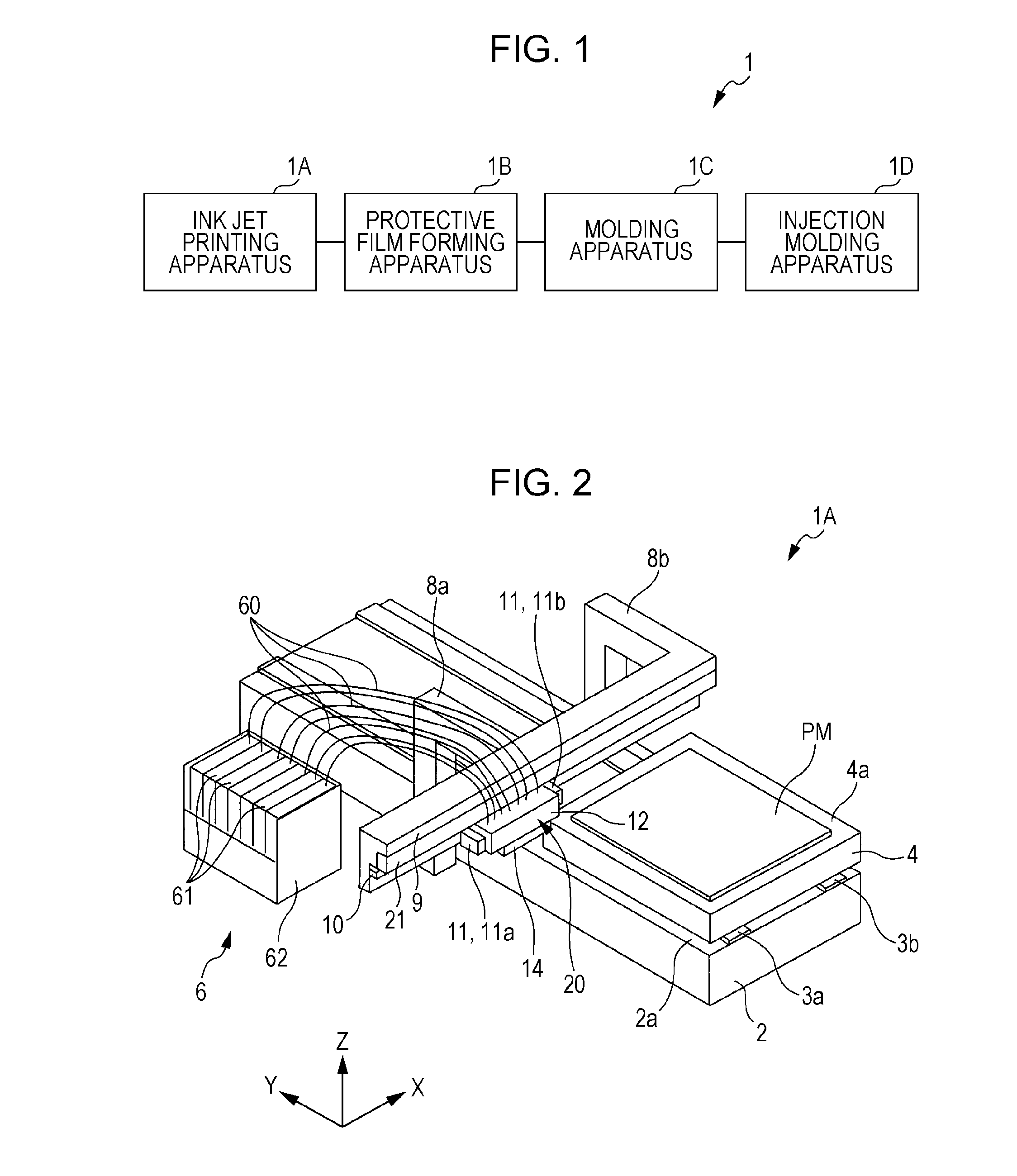
[0037]FIG. 1 is a drawing showing a system of manufacturing a printed matter in which the printing apparatus according to the invention is equipped. The manufacturing system 1 includes an ink jet printing apparatus 1A, a protective film forming apparatus 1B, a molding apparatus 1C, and an injection molding apparatus 1D, and a printing medium or a printed matter is transported between the apparatuses 1A to 1D by a transport apparatus, not shown in the drawings. The printing apparatus 1A among these apparatuses is an apparatus that includes an ink set that includes ultraviolet ray curable inks with seven mutually differing colors, a print head that discharges ink from the ink set as droplets, and an ultraviolet ray radiating section that radiates ultraviolet rays. The printed matter is manufactured while printing an image on the printing medium by a control section controlling the driving of the various members.
[0038]Meanwhile, the remaining apparatuses 1B to 1D carry out various post...
second embodiment
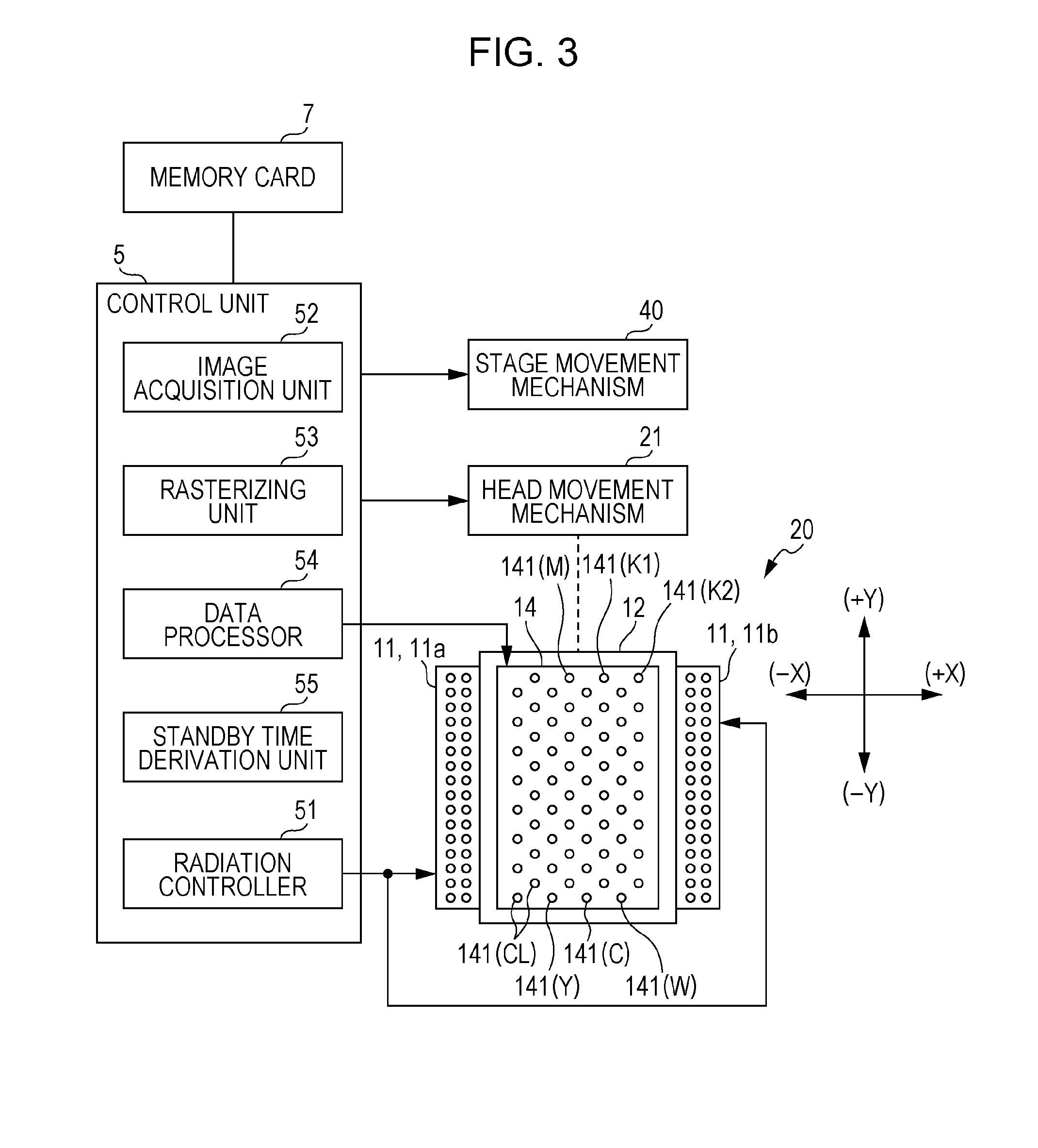
[0095]Before the formation operation of the first line layer starts, the head 20 is positioned at the standby position separated from the stage 4 to the (−X) axis direction side. Firstly, by the Y-axis motor being driven by the control section 5 during the starting of the formation operation, the stage 4 moves in the (−Y) axis direction, and the stage 4 is positioned so that the first area AR1 of the printing medium PM is positioned vertically below the reciprocation path of the head 20. In so doing, the preparation for the execution of the first scanning operation of the 16 scanning operations for forming the printed image is completed. Thus, ink is discharged in the form of liquid droplets from the printed image nozzle (nozzle other than the clear nozzle) 141 of the print head 14 toward the surface of the first area AR1 based on the printing data provided from the control section 5 while the head 20 moves in the forward direction (+X). Thus, as shown in FIG. 14, the line image A11...
PUM
 Abstract
Description
Claims
Application Information