Method of manufacturing optical fiber and apparatus of manufacturing the same

a manufacturing method and technology of optical fiber, applied in the direction of manufacturing tools, glass optical fiber, instruments, etc., can solve the problems of high construction cost, difficult to stably float the bare optical fiber in the direction changer tool, and high construction cost of new facilities. , to achieve the effect of stably floating the bare optical fiber

Active Publication Date: 2016-06-30
THE FUJIKURA CABLE WORKS LTD
View PDF7 Cites 4 Cited by
  • Summary
  • Abstract
  • Description
  • Claims
  • Application Information

AI Technical Summary

Benefits of technology

[0029]According to the aspects of the present invention described above, when the fluid is introduced into the guide groove from the blowout port of the direction changer to float the bare optical fiber, a Reynolds number of the fluid is in a range of 1200-3500, thereby, it is possible to stably float the bare optical fiber.

Problems solved by technology

The reason that the height of the system is a main factor which restricts productivity is because it is necessary to ensure a distance for sufficiently cooling a bare optical fiber which is obtained by drawing the optical fiber preform.
When a new facility including a building is built, the restriction can be relaxed; however, an enormous cost is required for building a new facility, and when it is required that productivity is further improved in the future, it is necessary that a new facility will be built at higher cost.
However, in the manufacturing method described in the above-described Japanese Unexamined Patent Application, it is not easy to stably float the bare optical fiber in a tool for the direction changer.

Method used


Image

  • Method of manufacturing optical fiber and apparatus of manufacturing the same
  • Method of manufacturing optical fiber and apparatus of manufacturing the same
  • Method of manufacturing optical fiber and apparatus of manufacturing the same

Examples


example 1

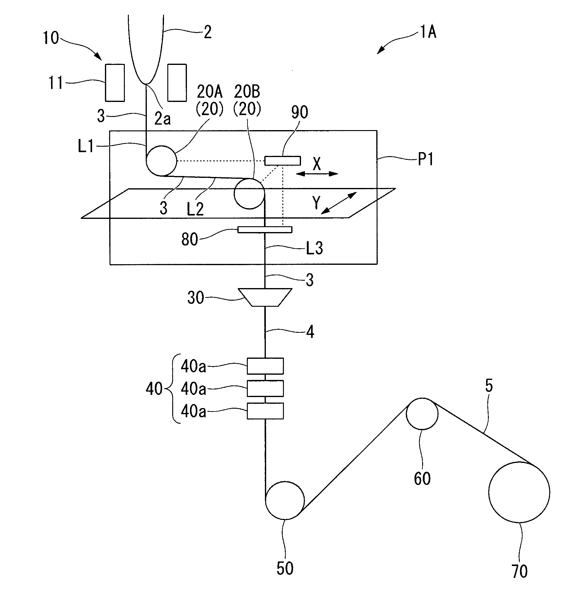
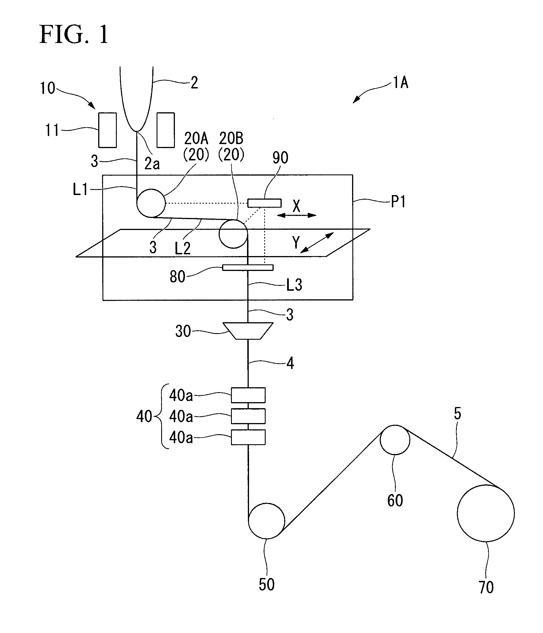
[0245]The manufacturing apparatus 1A shown in FIG. 1 was prepared.

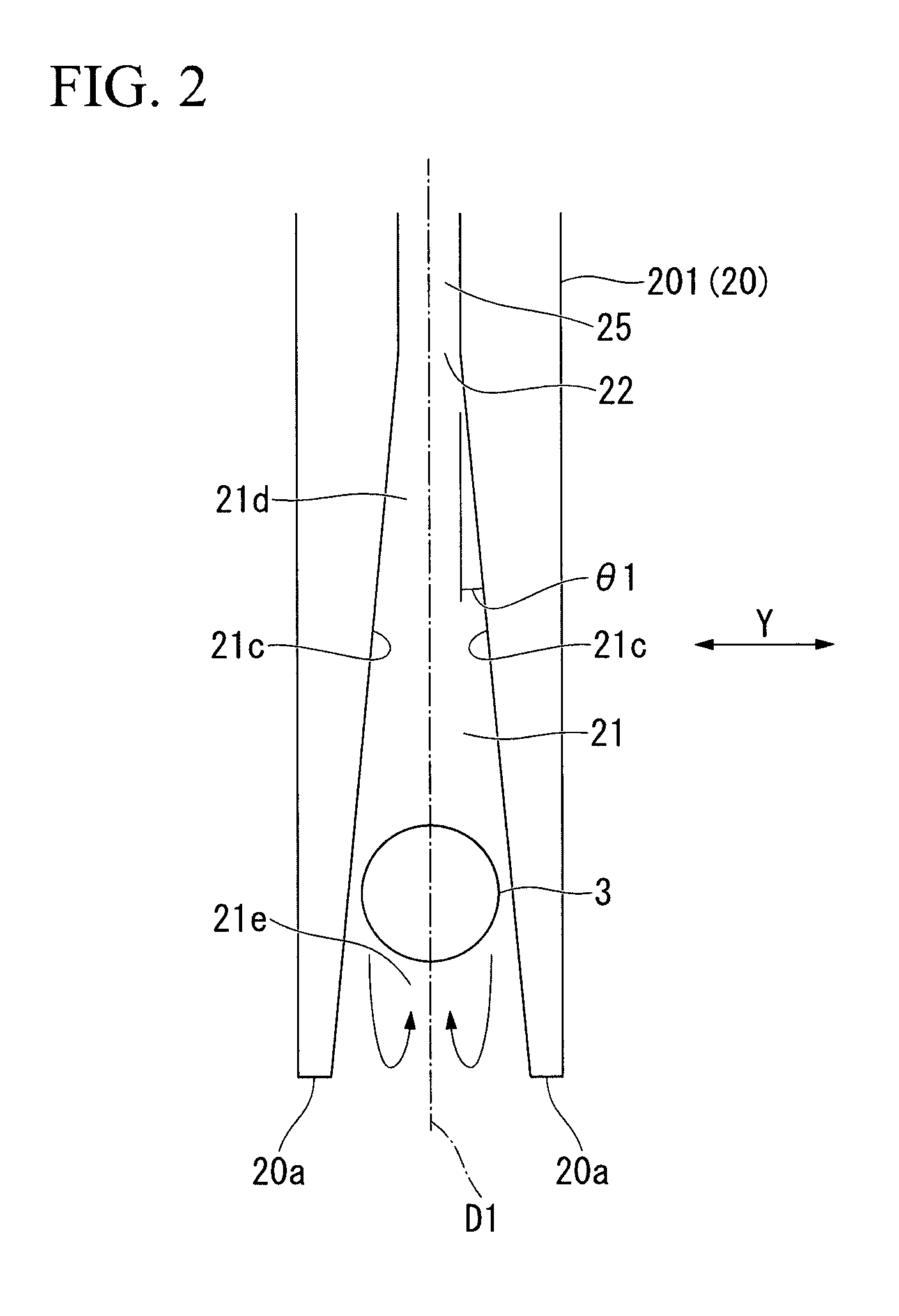
[0246]As the direction changers 20A and 20B, the direction changer 201 shown in FIGS. 3A and 3B was used. A width of the guide groove 21 is uniform in a depth direction.

[0247]A turning radius was approximately 62.5 mm. The width of the guide groove 21 (i.e., the width of the guide groove 21 at a position of an innermost periphery of the bare optical fiber 3 in a floating state) is 145 μm.

[0248]Re numbers (calculated values) of the direction changers 20A and 20B were approximately 2248.

[0249]The fluid introduced to the direction changers 20A and 20B was air, and the temperature thereof was room temperature (approximately 24° C.).

[0250]An introduced flow volume of the air was 100 liters / minute with respect to each of the direction changers 20A and 20B.

[0251]The first direction changer 20A was disposed in a position in which the temperature of the bare optical fiber 3 was approximately 1000° C.

[0252]When the direction ch...

example 2

[0260]In the manufacturing apparatus 1A shown in FIG. 1, an introduced flow volume of the fluid to the direction changers 20A and 20B was controlled by using the position sensor 80 and the control unit 90.

[0261]In other words, by the position sensor 80, the positional information of the bare optical fiber 3 (flotation amount in the second direction changer 20B) is obtained to output a detected signal to the control unit 90, and an introduced flow volume of the fluid to the direction changers 20A, 20B is controlled by the control unit 90.

[0262]As a control method, a PID controller is employed. Other conditions are in line with Example 1 to manufacture the optical fiber 5.

[0263]While manufacturing the optical fiber 5, variation of a linear speed is ±50 m / min at maximum, and variation of the drawing tension is ±25 gf at maximum.

[0264]However, in the direction changers 20A, 20B, since the flow volume of the air was controlled in a range of the Re number of 1200-3500, the flotation amoun...

example 3

[0266]In the manufacturing apparatus 1A shown in FIG. 1, as the direction changers 20A and 20B, a direction changer 201 having an Re-number profile shown in FIG. 8 is used. The width of the intermediate portion 26 in the blowout port 22 is 50 μm, and the minimum width of the first end portion 27 and the second end portion 28 is 45 μm.

[0267]As shown in FIG. 2, an inclination angle θ1 of the inside surface 21c of the guide groove 21 with respect to the radial direction D1 was 0.5°. A turning radius was approximately 62.5 mm.

[0268]The Re number at a portion excluding the inlet wire portion 23 and the outlet wire portion 24 (i.e., a portion corresponding to the intermediate portion 26) was 2200, and the Re number at the inlet wire portion 23 and the outlet wire portion 24 was 2500. The inlet wire portion 23 and the outlet wire portion 24 are portions in a circumferential direction corresponding to a range having an angle of 30° from each end.

[0269]When the direction changers 20A and 20B...


PUM

PropertyMeasurementUnit
Reynolds numberaaaaaaaaaa
lengthaaaaaaaaaa

Abstract

A method of manufacturing an optical fiber includes drawing an optical fiber preform and forming a bare optical fiber, disposing a coating layer formed of a resin on an outer circumference of the bare optical fiber, and curing the coating layer and obtaining an optical fiber. A direction of the bare optical fiber is changed by a direction changer in any position from drawing the optical fiber to disposing the coating layer, and the direction changer includes a guide groove which guides the bare optical fiber,

Description

CROSS REFERENCE TO RELATED APPLICATIONS[0001]Priority is claimed on Japanese Patent Application No. 2014-266308, filed on Dec. 26, 2014, the contents of which are incorporated herein by reference.BACKGROUND OF THE INVENTION[0002]1. Field of the Invention[0003]The present invention relates to a method of manufacturing an optical fiber and an apparatus of manufacturing the same.[0004]2. Description of Related Art[0005]FIG. 15 is a schematic view showing a schematic configuration of an example of an apparatus of manufacturing an optical fiber of the related art.[0006]The manufacturing apparatus includes a drawing unit 10 which forms a bare optical fiber 3 from an optical fiber preform 2, a cooling unit 120 which cools the bare optical fiber 3, a coating unit 30 which disposes a coating layer on the bare optical fiber 3 and forms an optical fiber intermediary body 4, and a curing unit 40 which cures the coating layer of the optical fiber intermediary body 4 to be an optical fiber 5.[000...

Claims


Application Information

Patent Timeline
Patent Type & Authority Applications(United States)
IPC IPC(8): C03C25/10C03B37/03G02B6/02
CPCC03C25/1055C03B2205/00C03B37/032G02B6/02395B65H57/04B65H2406/111B65H2701/32C03B37/0253C03C25/106Y02P40/57
Inventor OKADA, KENJI
Owner THE FUJIKURA CABLE WORKS LTD
Why Eureka
Try Eureka