Ground Milling Machine And Method For Adjusting The Stripping Plate Of A Ground Milling Machine

a ground milling machine and stripping plate technology, applied in the field of ground milling machines, can solve the problems of heavy wear on the working device of the milling drum, for example, the round shaft chisel, and the process is very time-consuming and needs to be repeated regularly, so as to achieve the effect of reliable method performan

Active Publication Date: 2016-06-30
BOMAG
View PDF0 Cites 11 Cited by
  • Summary
  • Abstract
  • Description
  • Claims
  • Application Information

AI Technical Summary

Benefits of technology

[0018]Ideally, controlling by the control device comprises actuating a valve, particularly a proportional valve, connected upstream the second actuator. The actuators are hydraulic cylinders in this case. Control via valves, particularly proportional valves, enables a particularly reliable performance of the method according to the present invention.

Problems solved by technology

The working devices of the milling drum, for example, round shaft chisels, are subject to heavy wear due to the comparatively great material stress and thus need to be replaced regularly during working operation.
However, said process is very time-consuming and needs to be repeated regularly due to the fact that friction values between the milling drum box and the stripping plate may change very rapidly during operation, for example.
However, this requires a robust parallel adjustment of the at least two actuators, since otherwise the stripping plate may get jammed or blocked on the milling drum box and may impair its functionality.
At the same time, such jamming or blocking increases wear to guiding elements for the stripping plate, which results in undesired reduction of its service life.

Method used


Image

  • Ground Milling Machine And Method For Adjusting The Stripping Plate Of A Ground Milling Machine
  • Ground Milling Machine And Method For Adjusting The Stripping Plate Of A Ground Milling Machine
  • Ground Milling Machine And Method For Adjusting The Stripping Plate Of A Ground Milling Machine

Examples


Embodiment Construction

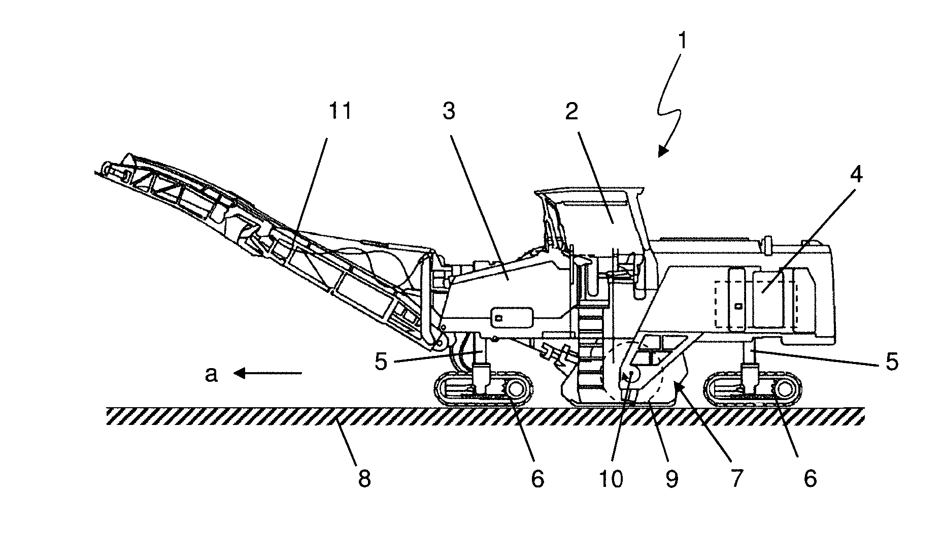
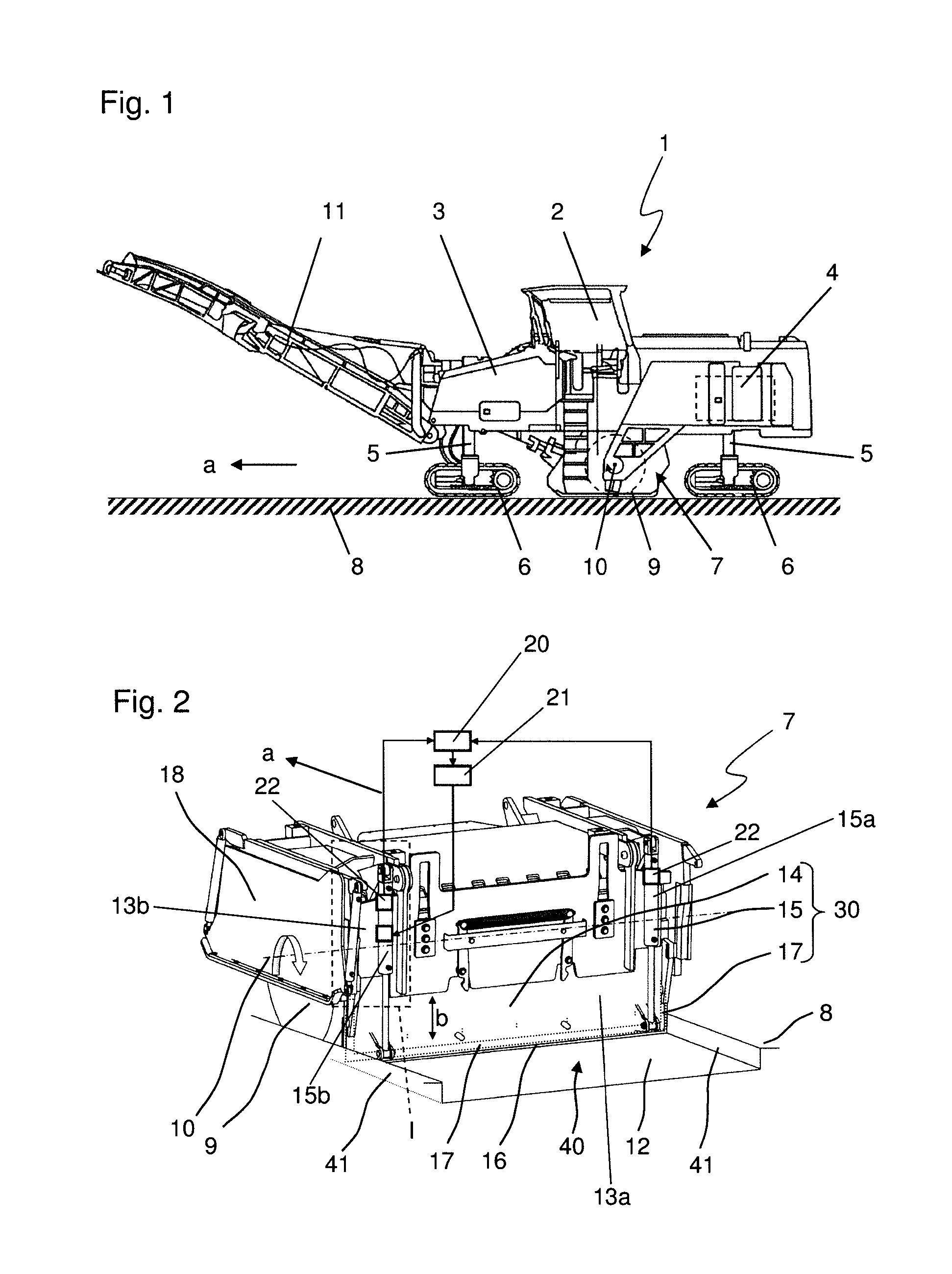
[0028]FIG. 1 shows a generic ground milling machine 1, in this case a road milling machine, respectively a cold milling machine. Said machine comprises an operator's platform 2, a machine frame 3, a drive engine 4 and travelling devices 6 connected to the machine frame via lifting columns 5. During operation of the ground milling machine 1, the ground 8 to be milled off is removed in the working direction a by means of a milling drum 9 which is mounted in a milling drum box 7 to be rotatable about a rotation axis 10 extending horizontally and transversely to the working direction a, the milling drum box 7 being connected to the machine frame 3 and arranged centrally between the front and rear travelling devices. The milled material is loaded to a transport vehicle not shown in the figures via a discharge belt 11 and is transported away by said transport vehicle.

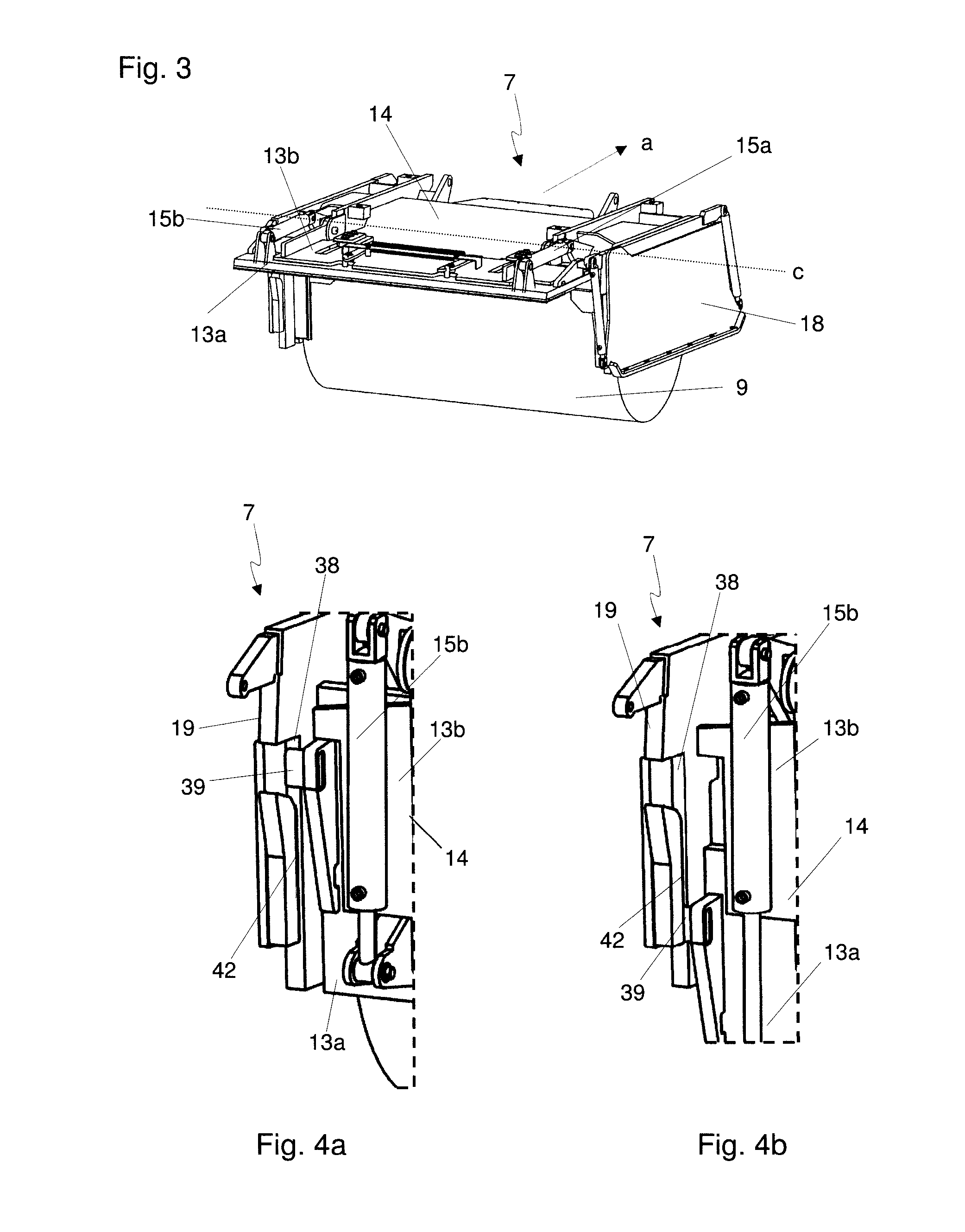
[0029]The structure and function of the milling drum box 7 are described in FIGS. 2 and 3, although the present invention i...


PUM


Abstract

The present invention relates to a ground milling machine, particularly a road milling machine, comprising a machine frame supported by travelling devices, a drive engine and a milling device arranged in a milling drum box, the milling drum box comprising a stripping plate which is height-adjustable by means of at least a first and a second actuator. Further, the present invention relates to a method for adjusting a stripping plate of a milling drum box of a ground milling machine, particularly a road milling machine. For the purpose of a reliable adjustment of the stripping plate, the present invention proposes using a monitoring device for detecting the adjustment of a first actuator and a control device for controlling the adjustment of a second actuator depending on the adjustment of the first actuator.

Description

FIELD OF THE INVENTION[0001]The present invention relates to a ground milling machine, particularly a road cold milling machine, as well as to a method for adjusting a stripping plate of a ground milling machine.BACKGROUND OF THE INVENTION[0002]Essential elements of such a ground milling machine are a machine frame supported by travelling devices, a drive engine providing the drive energy required for travelling and working operation, as well as a milling device. The milling device particularly is a milling drum, comprising a support tube equipped with a plurality of chisel devices on its outside jacket surface. The milling drum is usually arranged transversely to the working direction and horizontally with its rotation axis and mills the ground during working operation. Typical areas of application of generic ground milling machines are, for example, cold milling of bitumen surfaces, stabilizing and / or recycling of the ground or extraction of ground natural resources by means of so...

Claims


Application Information

Patent Timeline
Patent Type & Authority Applications(United States)
IPC IPC(8): E01C23/088G05D3/12
CPCG05D3/12E01C23/088G05B19/00
Inventor WACHSMANN, STEFFEN
Owner BOMAG
Why Eureka
Try Eureka