Locking device

a technology of locking device and coupling board, which is applied in the direction of couplings, instruments, machine supports, etc., can solve the problems of inaccurate performance of locking device, bulky locking device, difficult assembly, etc., and achieve the effect of increasing the precision of quick release coupling board and reducing the volume of the device for assembly or disassembly

Active Publication Date: 2016-06-30
SZ DJI OSMO TECH CO LTD
View PDF2 Cites 16 Cited by
  • Summary
  • Abstract
  • Description
  • Claims
  • Application Information

AI Technical Summary

Benefits of technology

[0015]Advantages of the present disclosure are such that the quick release coupling board can be slidably connected with the sliding assembly, and the locking device can lock the quick release coupling board to the sliding assembly. Thus, th

Problems solved by technology

The locking device can be bulky and difficult to assemble.
Further, the spring may swing when compressed or extended, causing it

Method used


Image

  • Locking device
  • Locking device
  • Locking device

Examples


Embodiment Construction

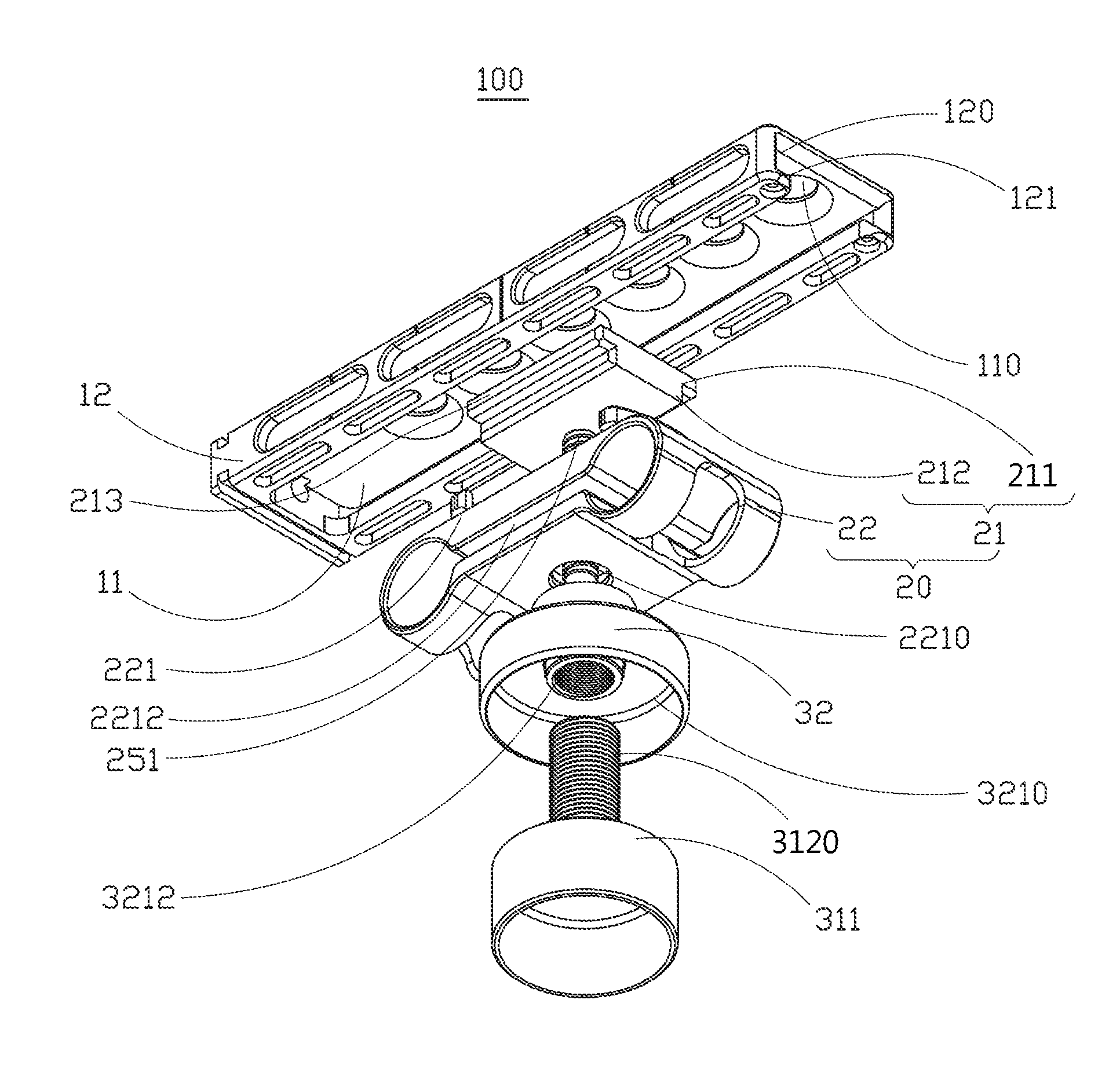
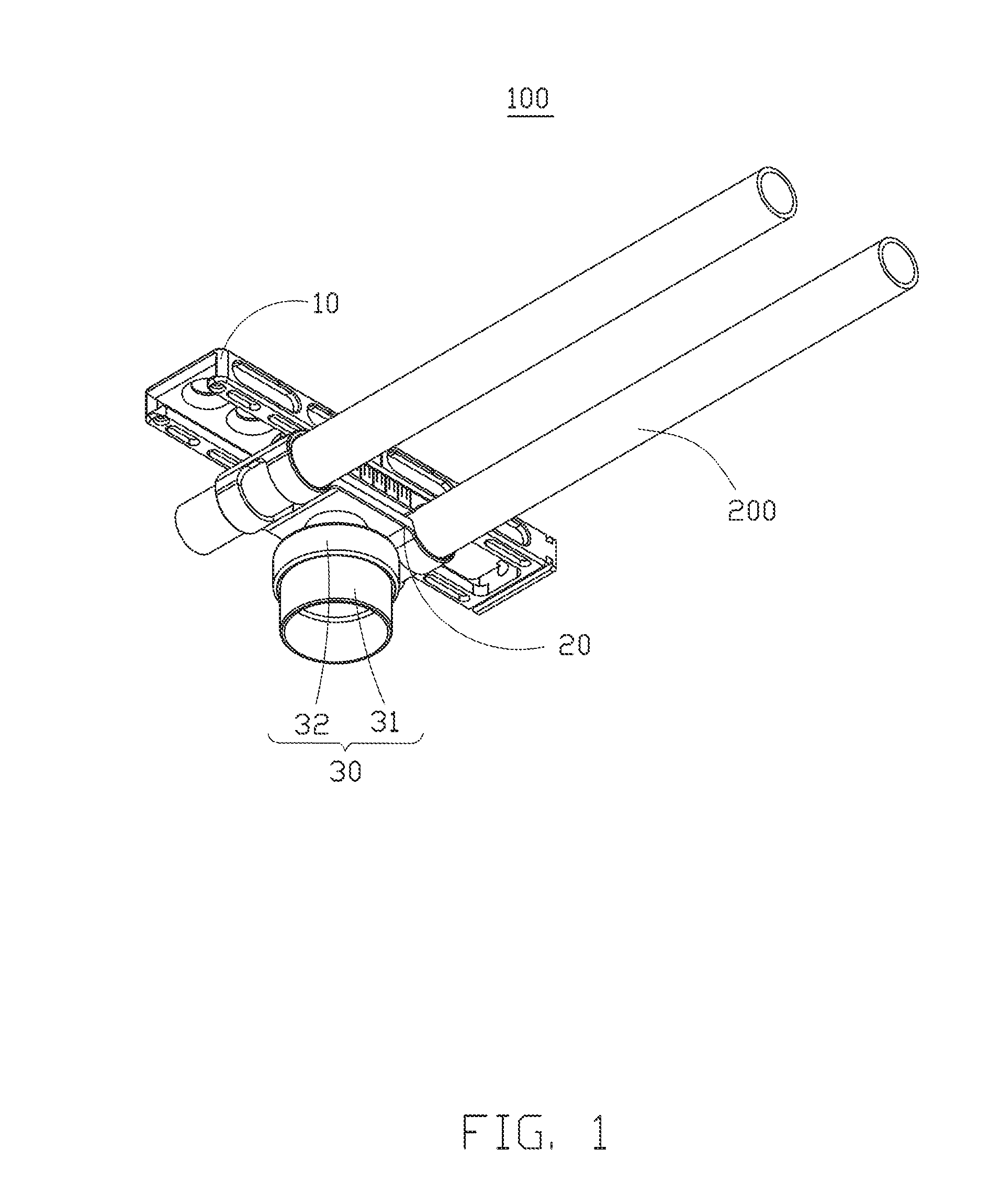
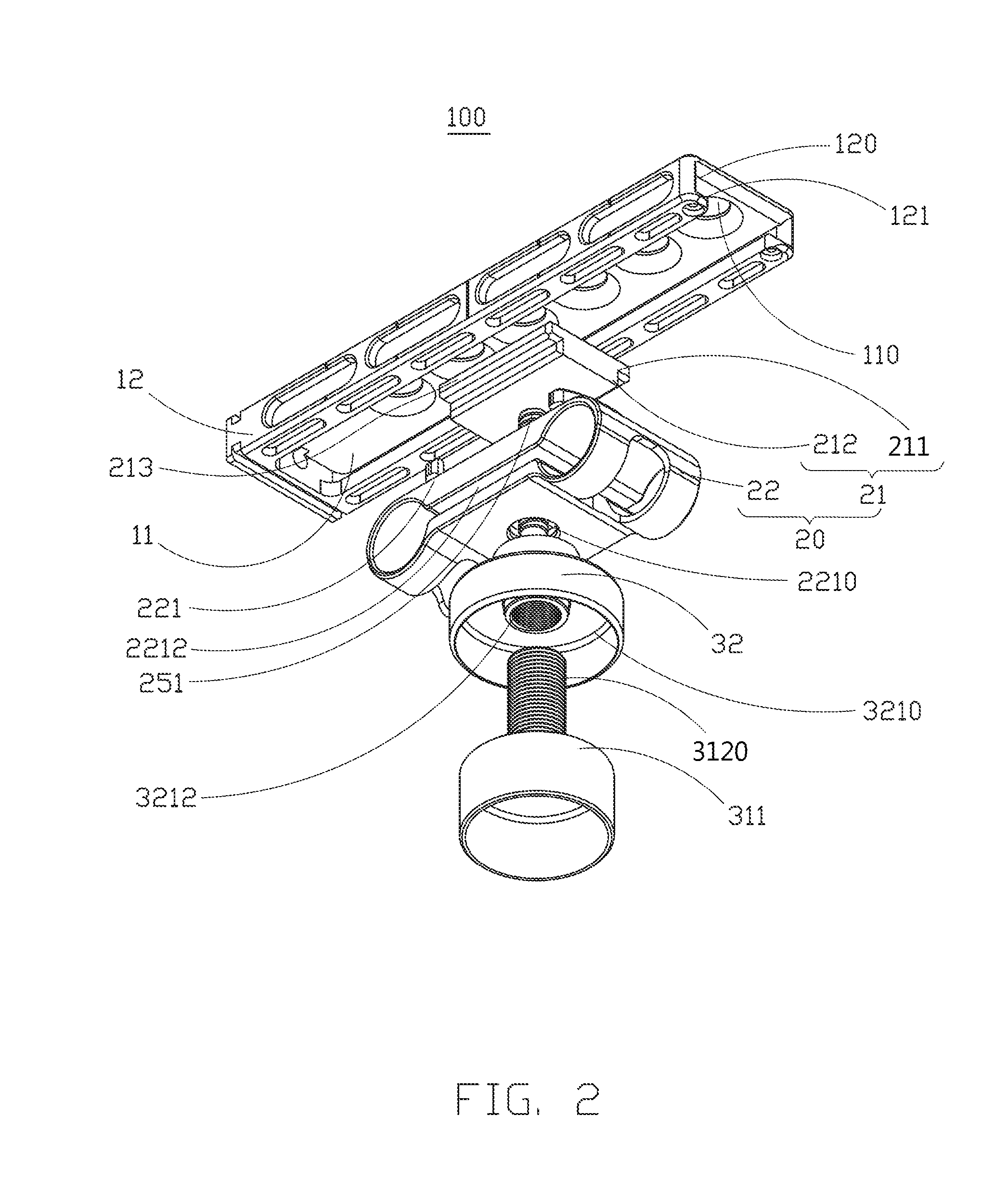
[0021]FIGS. 1-4 illustrate a locking device 100, which includes a quick release coupling board 10, a sliding assembly 20, and a locking assembly 30. In one embodiment illustrated in FIG. 1, the locking device 100 is mounted on a gimbal. The quick release coupling board 10 is slidably connected to the sliding assembly 20. The locking assembly 30 is connected to the sliding assembly 20 and is configured to lock the quick release coupling board 10 to the sliding assembly 20.

[0022]As illustrated in FIG. 2, the quick release coupling board 10 includes a bottom plate 11 and two opposite side walls 12. In the illustrated embodiment, the bottom plate 11 can be rectangular. The side walls 12 each extend perpendicularly downwards from a respective one of periphery sides of the bottom plate 11. The two side walls 12 each define a sliding slot 120. Each sliding slot 120 includes a blocking sheet 121. Both of the two blocking sheets are opposite to the bottom plate 11. Each blocking sheet 121 is...


PUM


Abstract

The present disclosure provides a locking device. The locking device may include a quick release coupling board, a sliding assembly slidably connected with the sliding assembly, and a locking assembly connected to the sliding assembly and configured to lock the quick release coupling board to the sliding assembly.

Description

FIELD[0001]The subject matter generally relates to locking devices.BACKGROUND[0002]When shutterbugs and vocational cameramen shoot photos outdoors, in order to select a better shooting angle and effect, they may assemble a camera or video camera on a quick mounting plate after adjusting an angle of a mounting gimbal, assemble the quick mounting plate mounted with the camera or video camera to a fixing support of the mounting gimbal, and lock the quick mounting plate by adjusting a locking device of the quick mounting plate.[0003]An existing locking device of the quick mounting plate may include a first locking element, a second locking element, and a plurality of springs disposed on the second locking element. The locking device can be bulky and difficult to assemble. Further, the spring may swing when compressed or extended, causing it to become loose when entering or exiting the quick mounting plate and causing an inaccurate performance of the locking device.SUMMARY OF THE INVENTI...

Claims


Application Information

Patent Timeline
IPC IPC(8): F16M11/04G03B17/56
CPCF16M11/048G03B17/561F16M11/045F16M11/041F16M13/00F16M2200/027
Inventor ZHAO, YAN CHONG
Owner SZ DJI OSMO TECH CO LTD
Why Eureka
Try Eureka