Single pole double throw switch

a single-pole, double-pole technology, applied in the direction of digital transmission, duplex signal operation, high-level techniques, etc., can solve the problems of circuit design, production cost increase, electric current consumption, etc., and achieve the effect of less time, simple structure and more competitive pri

Inactive Publication Date: 2016-06-30
LG INNOTEK CO LTD
View PDF9 Cites 0 Cited by
  • Summary
  • Abstract
  • Description
  • Claims
  • Application Information

AI Technical Summary

Benefits of technology

[0020]According to an exemplary embodiment of the present disclosure, the same operation as that of an active circuit may be implemented, even without using the active element. In addition, various advantageous effects as in the following may be obtained:
[0021](1) The SPOT switch according to an exemplary embodiment of the present disclosure may have more competitive price relating to development of a wireless system, because a pattern printed on the PCB is used.
[0022](2) The SPOT switch according to an exemplary embodiment of the present disclosure may be produced in less time, because no active element is used, and therefore a separate chip mount process and inspection is not required.
[0023](3) The SPDT switch according to an exemplary embodiment of the present disclosure may be modified according the frequencies and applications in use, and may be employed in various applications.
[0024](4) The SPDT switch according to an exemplary embodiment of the present disclosure has a simple structure, and therefore is easy to be applied. In addition, since passive elements are used, there is no risk of failure due to ESD.

Problems solved by technology

However, electrical current is consumed when performing the switching operation by applying voltage to active element (pin diode), and an additional chip such as a varistor is required to compensate a disadvantageous weakness in ESD (Electro Static Discharge).
In addition, the production cost may increase, in a case where various types of active elements, depending on the applications, are used to separate transmission signals and reception signals.
That is, use of the active elements such as the pin diode to separate by electrically switching transmission and reception signals may cause various problems in that the circuit design becomes complicated, energy is consumed, and the production cost is increased.

Method used


Image

  • Single pole double throw switch
  • Single pole double throw switch
  • Single pole double throw switch

Examples


Embodiment Construction

[0029]Hereinafter, an exemplary embodiment of the present disclosure will be described in detain with reference to the enclosed drawings.

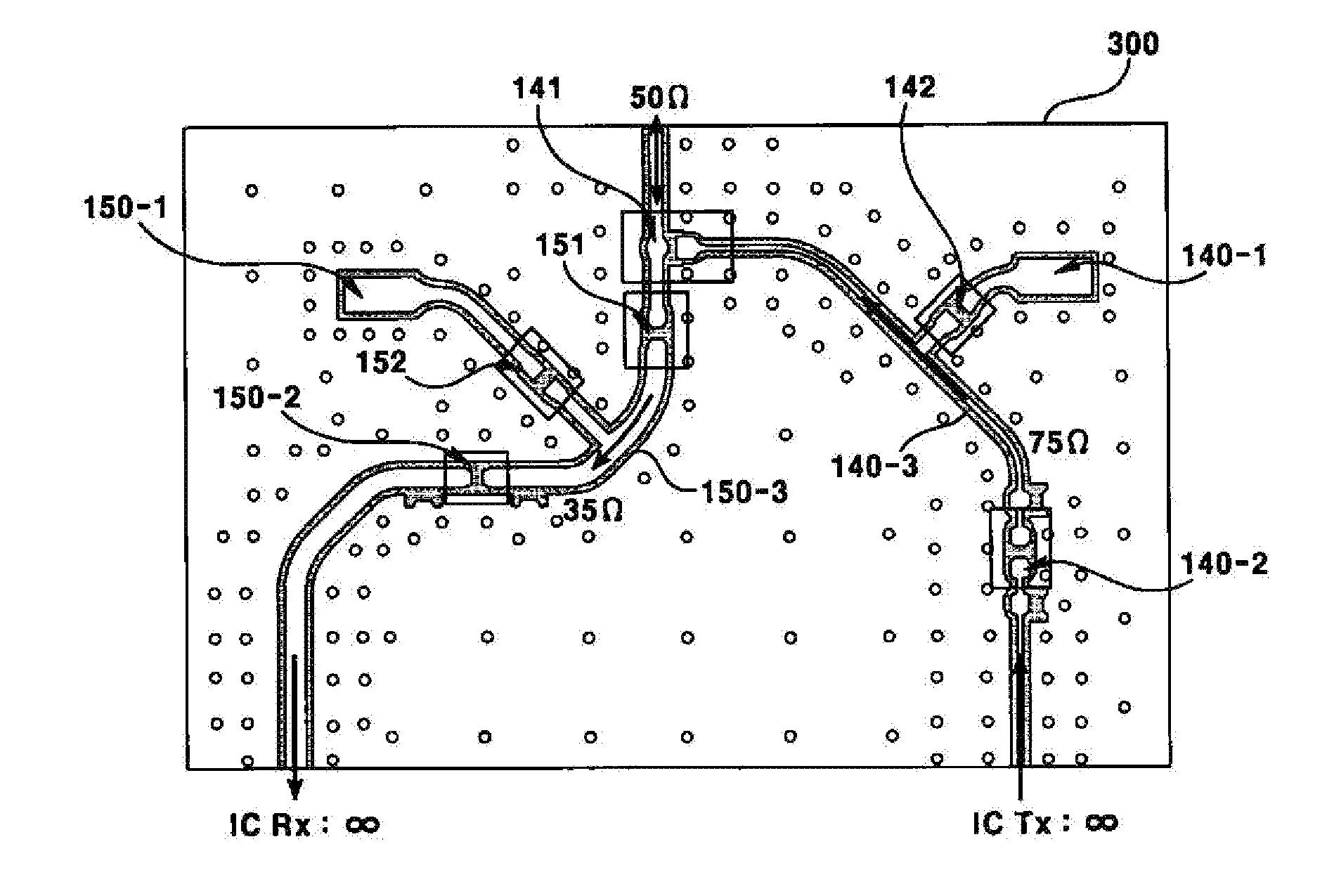
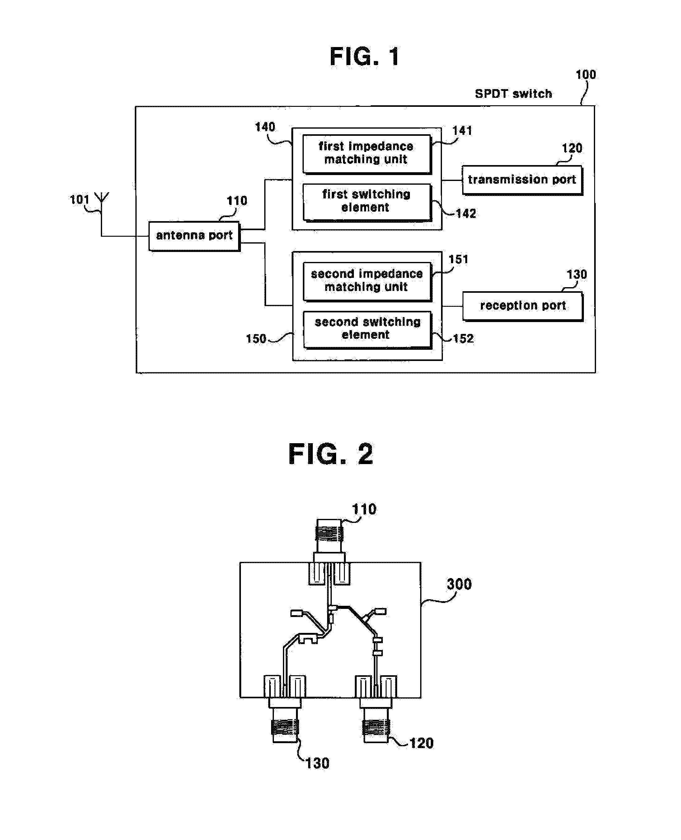
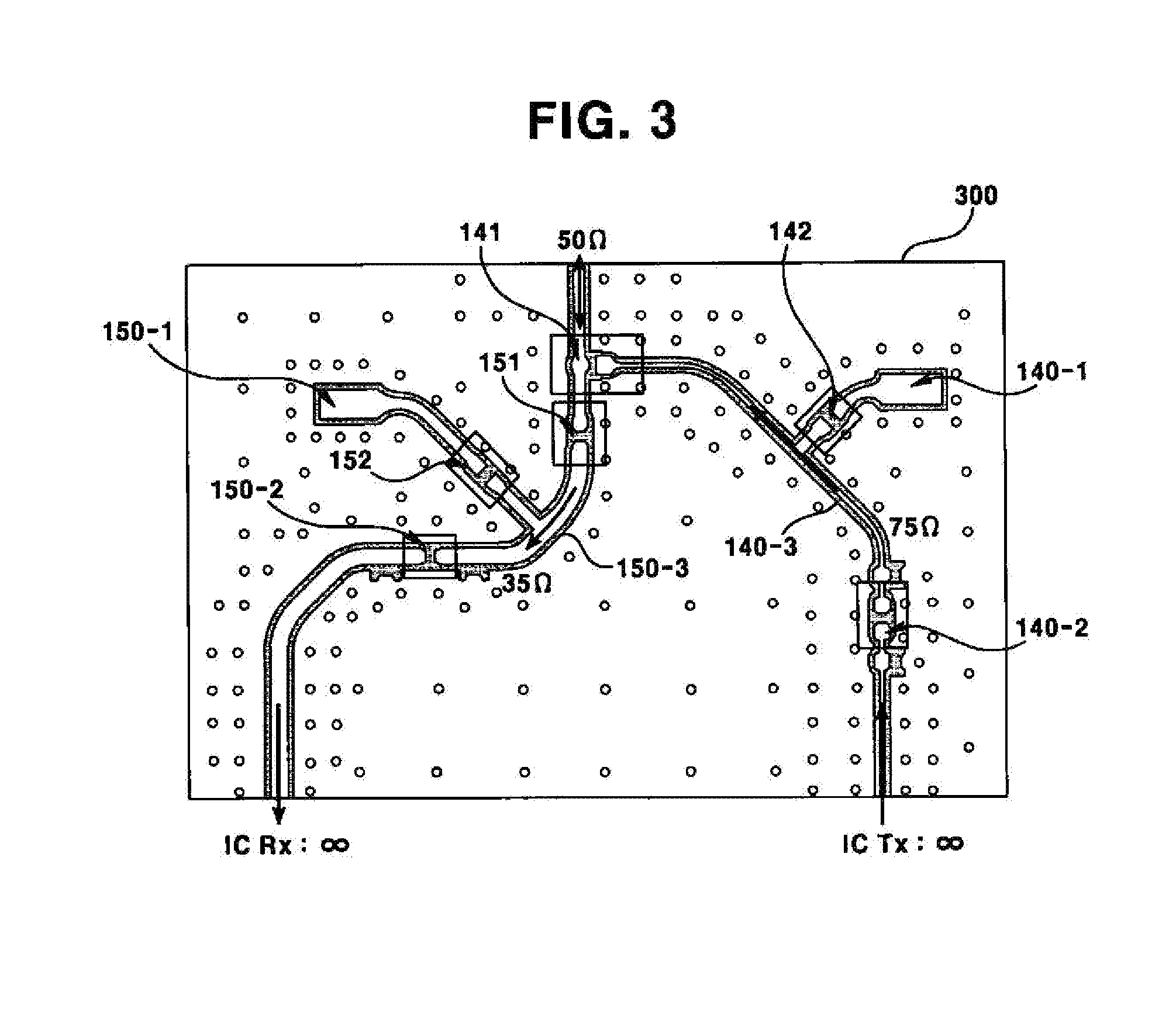
[0030]Referring to FIG. 1, the SPDT switch (100) according to an exemplary embodiment of the present disclosure may include an antenna port (110) connected to an antenna (101), a transmission port (120) receiving input of an RF signal to be transmitted through the antenna (101), a reception port (130) outputting an RF signal received through the antenna (101), a transmission unit (140) transmitting an RF signal inputted through the transmission port (120) to the antenna port (110), and a reception unit (150) transmitting an RF signal inputted through the antenna port (110) to the reception port (130). The SPDT switch (100) may transmit and receive an RF signal having a same frequency through the antenna (101).

[0031]The transmission unit (140) has a transmission terminal impedance, and the reception unit (150) has a reception terminal impedance, res...


PUM


Abstract

An SPDT switch configured to separate a transmission signal and a reception signal in order to transmit and receive signals in same frequency through an antenna, wherein difference between antenna impedance and reception terminal impedance of the reception unit is less than difference between antenna impedance and transmission terminal impedance, and difference between the transmission terminal impedance and the antenna impedance is less than a difference between the transmission terminal impedance and the reception terminal impedance. The transmission and reception terminal impedance may be specified using a pattern of an RF signal line printed on a PCB. The SPDT switch has more competitive price relating to development of a wireless system because a pattern printed on the PCB is used, and is easy to be applied since passive elements in simple structure are used, therefore having no risk of failure due to ESD.

Description

CROSS-REFERENCE TO RELATED APPLICATIONS[0001]Pursuant to 35 U.S.C. §119 (a), this application claims the benefit of earlier filing dates and rights of priority to Korean Patent Application No. 10-2014-0188435, filed on Dec. 24, 2014, and the contents of which are hereby incorporated by references in their entirety.BACKGROUND OF THE INVENTION[0002]1. Field of the Invention[0003]The present disclosure relates to an SPDT (Single Pole Double Throw) switch, and more particularly, to an SPDT switch that separates transmission signals and reception signals, in order to transmit and receive a signal in the same frequency in an RF (Radio Frequency) system transmitting and receiving wireless signals through an antenna.[0004]2. Description of Related Art[0005]Various techniques to separate transmission and reception signals by electrically switching are currently available according to separation characteristics thereof, for example, SPST (Single-Pole-Single-Throw), SPDT (Single-Pole-Double-Th...

Claims


Application Information

Patent Timeline
Patent Type & Authority Applications(United States)
IPC IPC(8): H04B1/56H03H7/38
CPCH03H7/38H04B1/56H04B1/44Y02D30/70
Inventor LEE, HYE SUNPARK, YOUNG HUN
Owner LG INNOTEK CO LTD
Why Eureka
Try Eureka