Industrial wood chipper knife and method for manufacturing an industrial wood chipper knife

a technology of industrial wood chips and industrial wood chips, which is applied in the direction of manufacturing tools, woodworking apparatus, rotary cutting tools, etc., can solve the problems of reducing the production of high-quality wood chips, significant downtime of chipping machines, and limited acceptance, so as to avoid deficiencies, improve production efficiency, and optimize geometry and size

Inactive Publication Date: 2019-03-21
CORTEX NORTH AMERICA CORP
View PDF0 Cites 0 Cited by
  • Summary
  • Abstract
  • Description
  • Claims
  • Application Information

AI Technical Summary

Benefits of technology

[0010]The object of this invention is to avoid deficiencies of the prior art and to introduce a chipper knife which has the optimized geometry and size compared to the prior art and can be manufactured at a more competitive price with the elimination of additional machining on over 50% of the surface after the heat treatment of the knife.
[0011]The present invention refers to a reversible knife and knife system for wood chipping with a smooth surface finish near the knife edge and improved stability, that allows for enhanced knife life (duration) and improved wood chipping performance. The top side of the knife utilizes a dual angle clamping style, where in which the knife is contacted on two distinct angles on each side of the top portion of the knife, providing a stable knife that will last longer than competing knives, while the bottom of the knife is defined by having two parallel lines that end in a ridge in the middle of the knife that is composed of straight lines, the angle between these lines is over 90 degrees.

Problems solved by technology

In recent years, disposable or reversible knives have gained acceptance in the industry due to improved safety and higher quality steel, but such acceptance has been limited due to knife stability and durability issues within the knife system, as well the high operating costs associated with disposable chipper knives.
These challenges can cause significant downtime in chipping machines and reduce the production of high quality wood chips.
The high costs have prohibited the disposable (reversible) knife technology to penetrate markets where the technology would provide large benefits.
The known designs have a tendency to allow the knife lo move or slip out of position.
Other challenges have been knives bending or twisting, which again reduces production time.
Known reversible knife systems are subject to over-torqueing when the damp that holds the knife is tightened down, or under torqueing and allowing the knife to come lose during operation.
Thus, the upper part of the clamping surface is subjected to a decreased clamping pressure and functional problems occur.
For example, wood fiber can enter into the space between a poorly clamped knife and its counter knife, thereby further degrading the performance of the knife.
Additional challenges with the prior art include the Chilean patent 49.918 which is a larger knife that has an aggressive deflection ridge that breaks up the high quality wood chips.
This action reduces the value of the wood chips during the wood chipping process and does not allow the wood chips to follow the natural flow of the cut.
When a knife begins to vibrate or move, the edge life decreases rapidly and the quality of the wood chips decrease.
The large size of this knife creates a leveraging action which also increases knife movement and reduces the duration of the edge.
This feature reduces the control of the wood chip and can break the wood chips into undesirable small pins chips.
This iteration of the patent has many challenges because of the extreme force on each side of the knife, which has caused the knife to break in half.
In another iteration of this knife, it is shaped like a Z. The large Z shaped knife has major stress concentration points that increase the risk of the knife breaking.
This knife design offers a much smaller knife, or low-volume knife, and a smoother chip transition ridge; however, the upper clamping portion is extremely wide and limits the thickness of the knife.
This limited thickness causes the knife to twist and bend after heavy wood chipping operations.
Also, the clamping on the top of the knife makes contact with the knife in 3 points, which is extremely difficult to guarantee proper clamping at all times. U.S. Pat. No. 8,082.958 specifically claims a concave area on the bottom of the knife leading to the crest of the edge on the knife.
This form dramatically increases the manufacturing costs because it is made with a custom tool or on a high cost form grinding machine.
These machines are very expensive and the grinding operation in the manufacturing accounts for a major source of the manufacturing cost.
Grinding the complete surface of the knife increases the cost and therefore reversible knives are sold at a much higher price.

Method used


Image

  • Industrial wood chipper knife and method for manufacturing an industrial wood chipper knife
  • Industrial wood chipper knife and method for manufacturing an industrial wood chipper knife
  • Industrial wood chipper knife and method for manufacturing an industrial wood chipper knife

Examples


Embodiment Construction

[0023]The knife and manufacturing process of the present invention is an improvement on existing designs by optimizing the size of the knife to eliminate twisting and bending associated with patent U.S. Pat. No. 8,082.958 and the leverage action that causes 49.918 to lose stability, while also drastically reducing the manufacturing cost by eliminating the need for expensive form grinders.

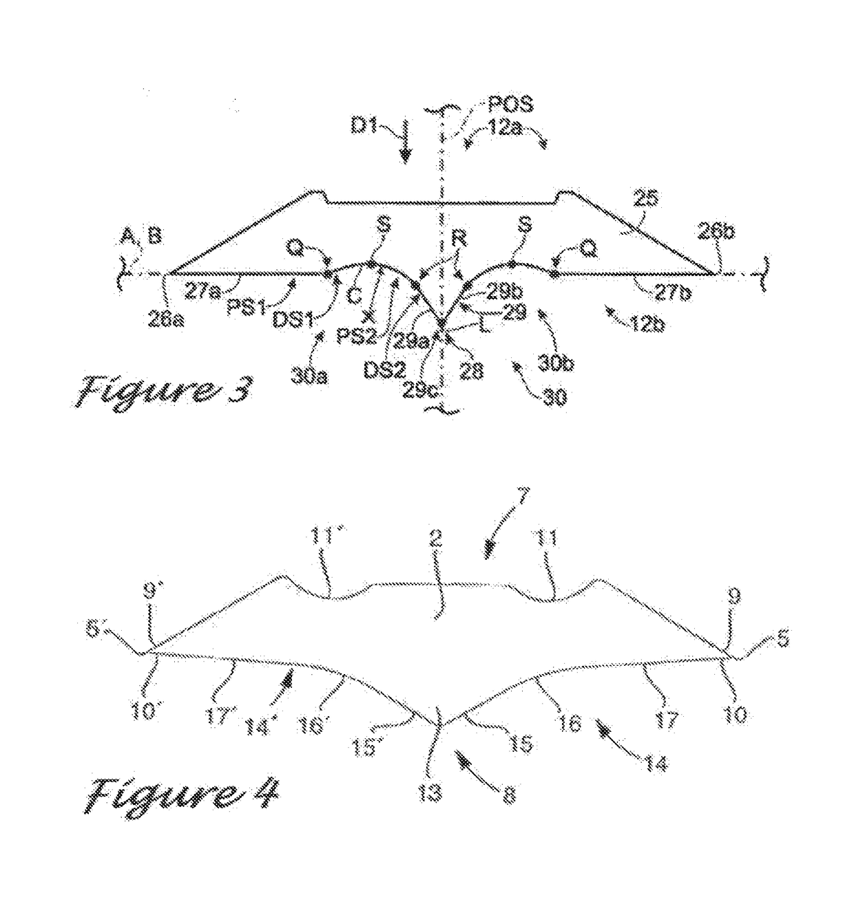
[0024]The current invention solves the problem of twisting and bending of the knife by utilizing a multy angle clamping zone that is narrower than patent U.S. Pat. No. 8.082.958 yet provides equal or greater clamping force. The invention provides more contact on the bottom of the knife, which allows the clamping area to be narrower and add thickness to the knife. This added thickness prevents the knife from bending or twisting during heavy operation.

[0025]The leverage action caused by the prior art in 49.918, which g increases the force on the knife and requires a large clamp to hold the knife in pl...


PUM


Abstract

A chipper has a knife clamped between a clamp and a counter knife that sits on a holder. The knife, damp, and counter knife are collectively positioned in a machined area formed in a holder that is in turn within a larger recess formed in a chipping disk or chipping drum.
A first fastener secures the knife holder to the chipping disk, a second fastener secures the clamp to the knife holder, and a third fastener secures the counter knife lo the knife holder. The knife comprises a ridge which is formed by the termination in two straight lines which form a triangle shape on the bottom of the knife. These straight lines reduce the manufacturing cost of the knife and provide support for the knife to locate. The knife is also manufactured without 100% grinding of all services, which is unique in that this reduces manufacturing costs dramatically.

Description

FIELD OF THE INVENTION[0001]This invention relates to improvements in the manufacturing of reversible chipper knives and an optimized design for the ridge on the bottom of the knife, which improves knife stability as well as reduces the manufacturing costs.BACKGROUND OF THE INVENTION[0002]Chippers are machines capable of chipping various sizes and types of wood species into particles known generally as chips. The chips are used, primarily, as raw material for pulp manufacturing. The wood species that are cut into chips for pulp production vary greatly in size and type, i.e. some woods are very hard and some arc very soft. There arc two broad areas of chip production; primary chip manufacturing where chips are cut out of whole log trunks, and secondary chip manufacturing where chips are produced from residual wood, i.e. trimmings from sawmills.[0003]In recent years, disposable or reversible knives have gained acceptance in the industry due to improved safety and higher quality steel,...

Claims


Application Information

Patent Timeline
Patent Type & Authority Applications(United States)
IPC IPC(8): B27G13/04B27L11/00
CPCB27G13/04B27L11/005
Inventor CARPENTER, TRENTON LEE
Owner CORTEX NORTH AMERICA CORP
Why Eureka
Try Eureka