
Breather for permanent aluminium-casting mould

a technology of aluminium casting mould and breather, which is applied in the field of new vents, can solve the problems of reducing the productivity of castings, compromising quality, and losing function, and achieves the effects of reducing consumption, reducing costs, and reducing costs

Active Publication Date: 2014-09-02
ZANATTA JEANLIS BRITO
View PDF9 Cites 3 Cited by
  • Summary
  • Abstract
  • Description
  • Claims
  • Application Information

AI Technical Summary

Benefits of technology

[0015]Having in mind the maximization of resistance to clogging, caused by penetration of aluminium, the unique and revolutionary vent was idealized, wherein it is able to provide technical advantages due the increase of quality of the castings and, at the same time, achieve higher productivity gains when compared with the three types of vent that define the prior state of art.
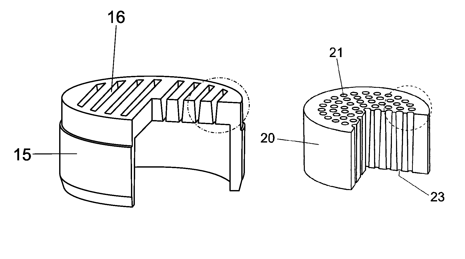
[0016]This increase in efficiency of the type of vent of the present invention is provided by the unique constructive arrangement of the grooves, which instead of presenting holes with parallel or inclined dimensions in a standard configuration, as exemplified above, are provided with an inverted inclination wherein the larger dimension is on the outer face of the vent, and not inside.
[0018]Another factor of great importance is the economic impact provided by this new type of vent, due the reduction of costs, since the manufacturing process—unlike the machining and sintering processes that predominate in the related art—allows achieve more competitive prices, and above all, in terms of reducing consumption, the new type has the unique advantage of reduction of the clogging frequency, with the direct benefit of a longer service life for the vents.
[0019]Importantly, the casting process used to manufacture this new type of vent offers two other technical advantages: the first concerns the possibility of making it both with holes shaped like grooves or with ordinary holes, wherein their shape has a inclination, in case of grooves, and a taper, in case of holes, both inverted with respect to the standard types known in prior state of art, and their dimensions can vary widely, always complying with the inverted inclination and / or taper. The second advantage lies in the dynamism and flexibility of this process, because it is possible manufacture the vent using several kinds of materials: carbon steel alloys, stainless steel alloy, brass alloys and bronze alloys.

Problems solved by technology

As is known to those skilled in the art, after an early period of production the aluminium starts to penetrate in the holes of the vents, clogging the air outlets, therefore causing them to lose their function.
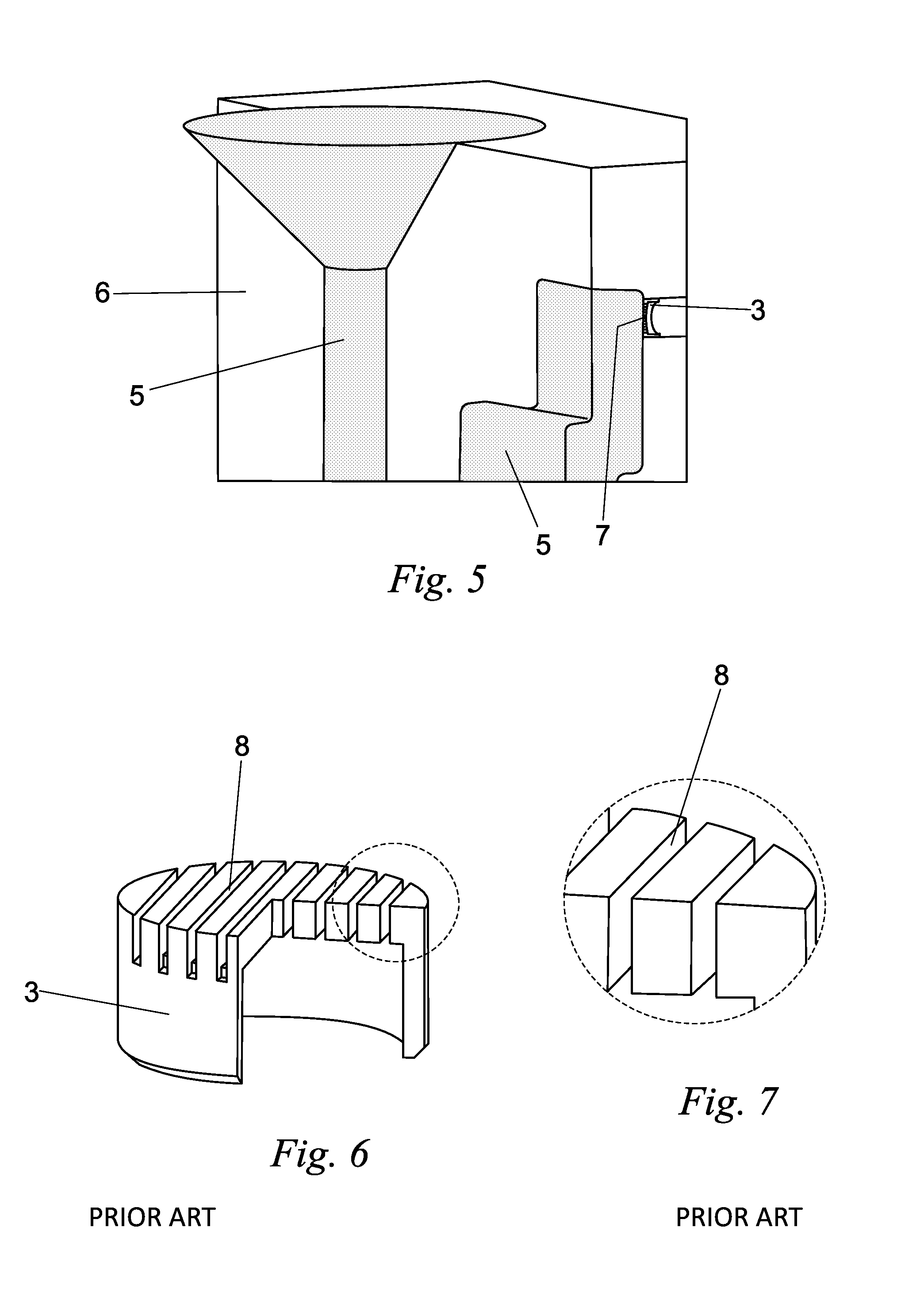
The major effect of this scenario is the formation of defects due to porosity or the deformation of the part, compromising its quality and hence reducing the productivity of the castings, according to what is illustrated in FIG. 5.
At the time when the aluminum comes into contact with the vent during the mould filling stage, it is in liquid state at a temperature of 740° C. In this condition, the aluminium has fluidity and it can penetrate through the vent holes, causing their clogging with burrs.
Commonly, the smelters are forced to replace the clogged vents almost in a daily basis, because the aluminium difficults the simple cleaning of the holes.
Thus, besides the loss of quality of their castings, the smelters are also penalized with higher costs due the consumption of vents with small lifetime.
Another important aspect that contributes to the inefficiency of production are the losses summed with frequent stops of the machinery, in order to replace the damaged vents, since this is a work that requires a lot of runtime.

Method used


Image

  • Breather for permanent aluminium-casting mould
  • Breather for permanent aluminium-casting mould
  • Breather for permanent aluminium-casting mould

Examples


Embodiment Construction

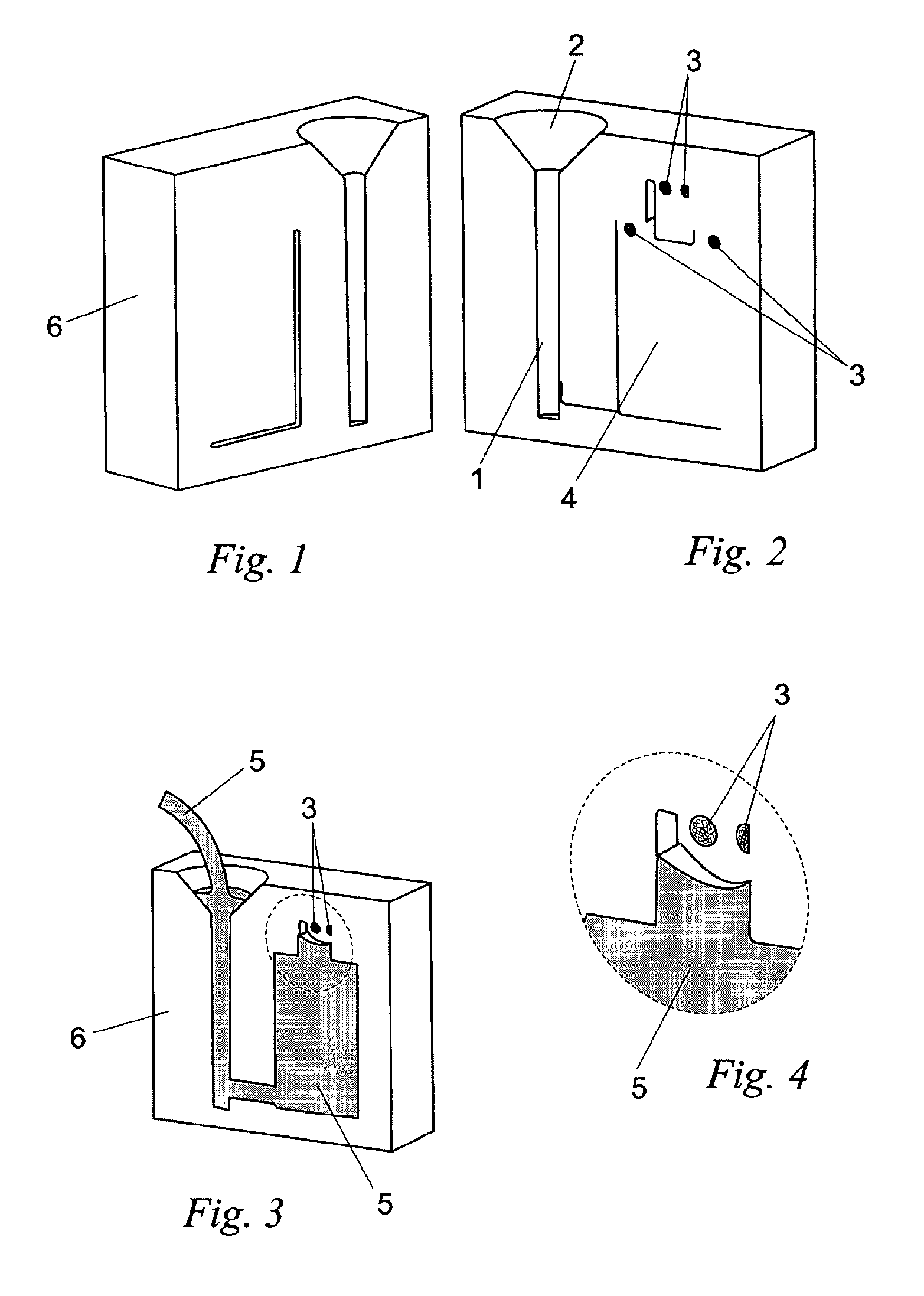
[0033]According to the figures and their details, the example of permanent mould (6) having pouring by gravity consists of a pouring basin (2) connected to a filling channel (1) connected to a cavity (4) whose top is provided with vents (3) for air outlet.

[0034]To the extent that the aluminium (5) is poured into the mould (6) filling the cavity (4), at the end of the operation the aluminium comes into contact with the outer face (7) of the vent (3).

[0035]The vent (3) is known in the prior art and is manufactured with parallel grooves (8).

The vent (9) is known in the prior art and is manufactured with parallel channels (10).

[0036]The vent (11) is known in the prior art and is manufactured with standard inclined grooves (12), so that the smaller dimension (13) is on the outer surface of the vent (11), where the angle A indicates the direction of inclination.

[0037]The vent (3) installed on the mould (6), at the time the aluminium clogs said vent (3) known in the prior art, penetrating ...


PUM

PropertyMeasurementUnit
temperatureaaaaaaaaaa
pressureaaaaaaaaaa
porosityaaaaaaaaaa

Abstract

The patent relates to the field of metallurgical products and comprises a cylindrical body (15) provided with a plurality of slots (16), with a taper “A” designed such that the larger opening (18) is at the outer surface of the breather (15) and the smaller opening (19) is located internally with respect to the breather (15), so that the aluminum component (5), when removed from the mold (6), brings with it the burr (17), leaving the slots (16) of the breather (15) always free, and also a breather (20) comprising a cylindrical body constituted from a plurality of holes (21), with a conicity “A” designed such that the larger opening (22) is at the outer surface of the breather (20) and the smaller opening (23) is located internally with respect to the breather (20).

Description

CROSS REFERENCE TO RELATED APPLICATION[0001]This application is a national stage entry of PCT / BR2011 / 000178 filed Jun. 8, 2011, under the International Convention.FIELD OF THE INVENTION[0002]This specification of patent refers to a new vent, especially a device used in permanent moulds for casting of aluminium, innovative, and having important technological and functional design improvements, with the most modern engineering concepts and according to the required technical rules and specifications, having intrinsic characteristics, resulting in a number of real and extraordinary technical, practical and economic advantages.BACKGROUND OF THE INVENTION[0003]The production of aluminium castings using permanent moulds can have three types of metal pouring: with high pressure, by gravity, and with low pressure against gravity, wherein the latter two processes need vents for air outlet.[0004]During the process of filling the mould, the molten metal tends to drag and trap the gases (air) t...

Claims


Application Information

Patent Timeline
Patent Type & Authority Patents(United States)
IPC IPC(8): B22C9/06B22C7/06
CPCB22C9/067Y10S425/812B22C7/065
Inventor ZANATTA, JEANLIS, BRITO
Owner ZANATTA JEANLIS BRITO
Learn More