
Ceramic honeycomb filter and manufacturing method thereof

A ceramic honeycomb and filter technology, applied in membrane filters, ceramic products, chemical instruments and methods, etc., can solve the problem of reducing the effective area, unable to meet the PM capture performance and pressure loss characteristics, differential pressure loss characteristics, etc. problem, to achieve the effect of high capture performance

Inactive Publication Date: 2015-10-21
HITACHI METALS LTD
View PDF11 Cites 0 Cited by
  • Summary
  • Abstract
  • Description
  • Claims
  • Application Information

AI Technical Summary

Problems solved by technology

However, with the cells 62a provided with the plugs 63b having a relatively large opening area to ensure PM trapping performance, the effective area of ​​the cell walls of the ceramic honeycomb filter 60 serving as a filter decreases, resulting in poor pressure loss characteristics , so that PM capture performance and pressure loss characteristics cannot be satisfied at the same time

Method used


Image

  • Ceramic honeycomb filter and manufacturing method thereof
  • Ceramic honeycomb filter and manufacturing method thereof
  • Ceramic honeycomb filter and manufacturing method thereof

Examples


example 1

[0159] Using bonding equipment 80 [see Figures 15(a) to 15(e) ], two 150 mm long dry ceramic honeycomb structures C are displaced by 0.3 in each cell wall thickness direction [in each of the X and Y directions shown in Fig. The hole wall spacing is arranged end-to-end. No adhesive material is used on the opposite end surfaces. The arranged two dry ceramic honeycomb structures were sintered in a sintering furnace at a maximum temperature of 1410 °C for 8 days. A slurry including cordierite, a binder, and water was applied to the peripheral surface of the sintered ceramic honeycomb structure and dried to manufacture a ceramic honeycomb filter having an outer diameter of 270 mm and a length of 300 mm.

example 2

[0161] A ceramic honeycomb filter having an outer diameter of 270 mm and a length of 300 mm was manufactured in the same manner as in the example, except that the two desiccators were displaced by 45° in the direction of rotation around their central axis with their cell walls.

example 3

[0163] Adopt bonding equipment 80, two 150mm long dry ceramic honeycomb structures C with their cell walls on each cell wall thickness direction [in each of the X and Y directions shown in Fig. 2 (a) ] displaced by 0.1 times the cell wall spacing are arranged end-to-end via a bonding material comprising a cordierite forming material, a binder and water. The bonding material is a dry ceramic honeycomb structure C [see Figure 14(a) with 14(b) ] The end surface of the hole is 2 times thicker than the spacing of the holes. The arranged two dried ceramic honeycomb structures were sintered in a sintering furnace at a maximum temperature of 1410° C. for 8 days to manufacture a ceramic honeycomb filter with an outer diameter of 266.7 mm and a length of 301 mm.


PUM

PropertyMeasurementUnit
surface roughnessaaaaaaaaaa
thicknessaaaaaaaaaa

Abstract

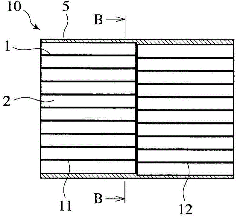
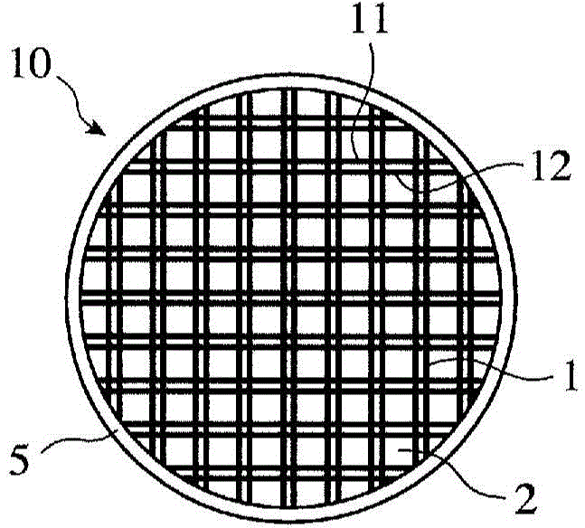
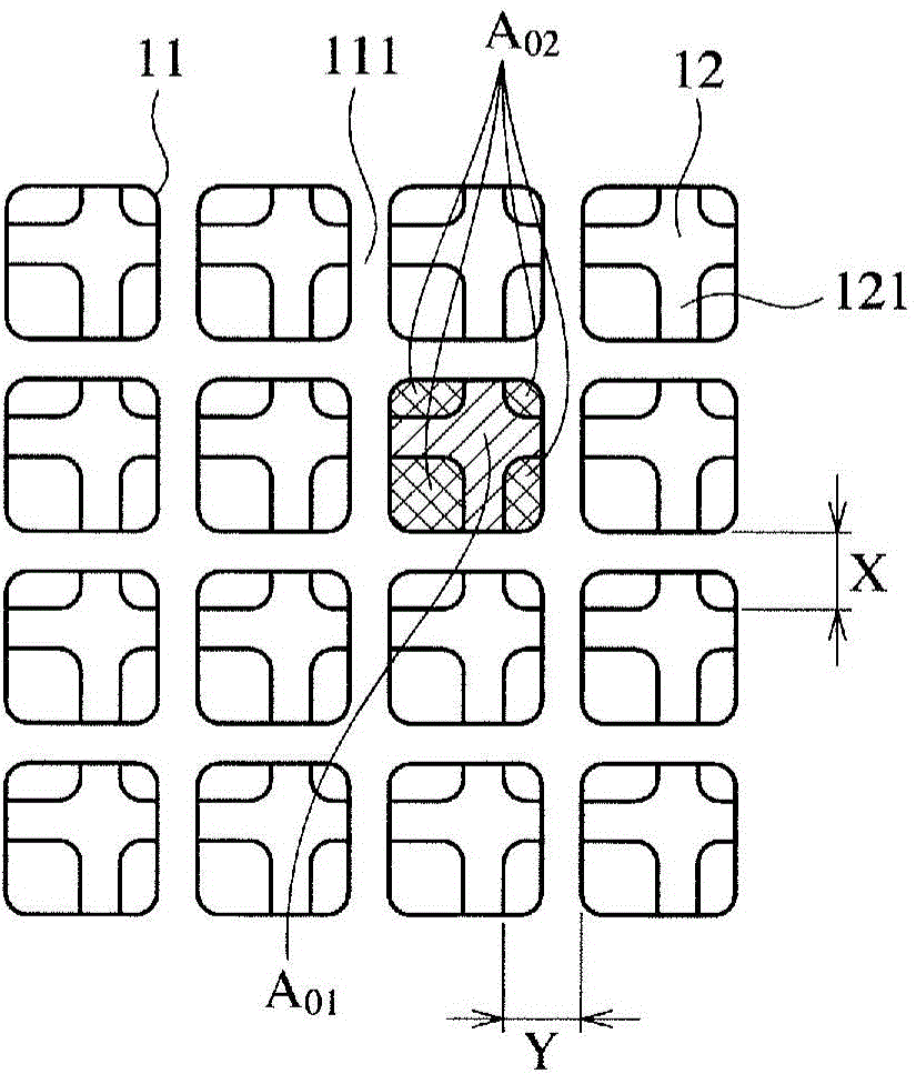
A ceramic honeycomb filter for removing fine particles in exhaust gas, characterized in that: a plurality of ceramic honeycomb structures each having many cells separated by porous partition walls are connected in an axial direction, with the end faces thereof being joined to each other; at least part of the partition walls of at least one set of adjoining ceramic honeycomb structures are joined to each other in a mutually shifted state; when the opening area of one cell in the cross-section perpendicular to the axial direction of the upstream one of the adjoining ceramic honeycomb structures is expressed as A01, and the opening area of the one cell after being reduced as a result of being narrowed by the upstream end face of the partition walls of the downstream ceramic honeycomb structure is expressed as A02,the average of the opening area ratios A0 (=A02 / A01) of the respective cells in any contiguous 5 cells×5 columns (=25 cells) is equal to or less than 0.9; and the roughness (the maximum height is Rz) of each of the partition wall end face and the partition wall surface of the downstream ceramic honeycomb structure is equal to or larger than 15µm.

Description

technical field [0001] The present invention relates to a ceramic honeycomb filter for cleaning exhaust gas exhausted from an internal combustion engine such as a diesel engine and a method for manufacturing the same. Background technique [0002] Exhaust gas exhausted from an internal combustion engine such as a diesel engine or the like contains a large amount of particulate matter (hereinafter referred to as "PM"). Since the PM discharged into the air causes environmental pollution, the filter is used to capture the PM. Such as Figure 11(a) with 11(b) As shown, for example, the ceramic honeycomb filter 50 includes a ceramic honeycomb structure including a large number of cells separated by porous cell walls 51, and alternately arranged at the exhaust gas inlet side end a and the exhaust gas outlet side end The plugs in the holes on part b (upstream side plug 53a and downstream side plug 53b), through alternately arranged outlet side end blocking holes 52a and inlet sid...

Claims


Application Information

Patent Timeline
Patent Type & Authority Patents(China)
IPC IPC(8): B01D39/20B01D46/00C04B37/00F01N3/021
CPCB01D46/247B01D2279/30C04B35/195C04B38/0006C04B2111/00793C04B2111/0081C04B2235/3217C04B2235/3445C04B2235/349B01D46/2484B01D46/2482B01D46/2478C04B38/0054C04B38/0074C04B38/0655B01D46/2474B01D46/249B01D46/2486B01D46/2455
Inventor 冈崎俊二曾我航小松顺二
Owner HITACHI METALS LTD
Learn More