
Method and device to adjust a predetermined radial tip clearance of a turbomachine blade

一种转子叶片、流体机械的技术,应用在机械设备、叶片的支承元件、金属加工设备等方向,能够解决加工精度损失、低加工精度、流体机械功率影响等问题,达到避免改装时间的效果

Active Publication Date: 2014-05-21
SIEMENS ENERGY GLOBAL GMBH & CO KG
View PDF8 Cites 1 Cited by
  • Summary
  • Abstract
  • Description
  • Claims
  • Application Information

AI Technical Summary

Problems solved by technology

The use of such imitation wheels is of course accompanied by lower machining accuracy, which can have a negative impact on the performance of fluid machines
In addition, there is the possibility of machining rotor blades without discs by means of so-called single-rotor blade grinding installations, which results in additional losses in machining accuracy

Method used


Image

  • Method and device to adjust a predetermined radial tip clearance of a turbomachine blade
  • Method and device to adjust a predetermined radial tip clearance of a turbomachine blade
  • Method and device to adjust a predetermined radial tip clearance of a turbomachine blade

Examples


Embodiment Construction

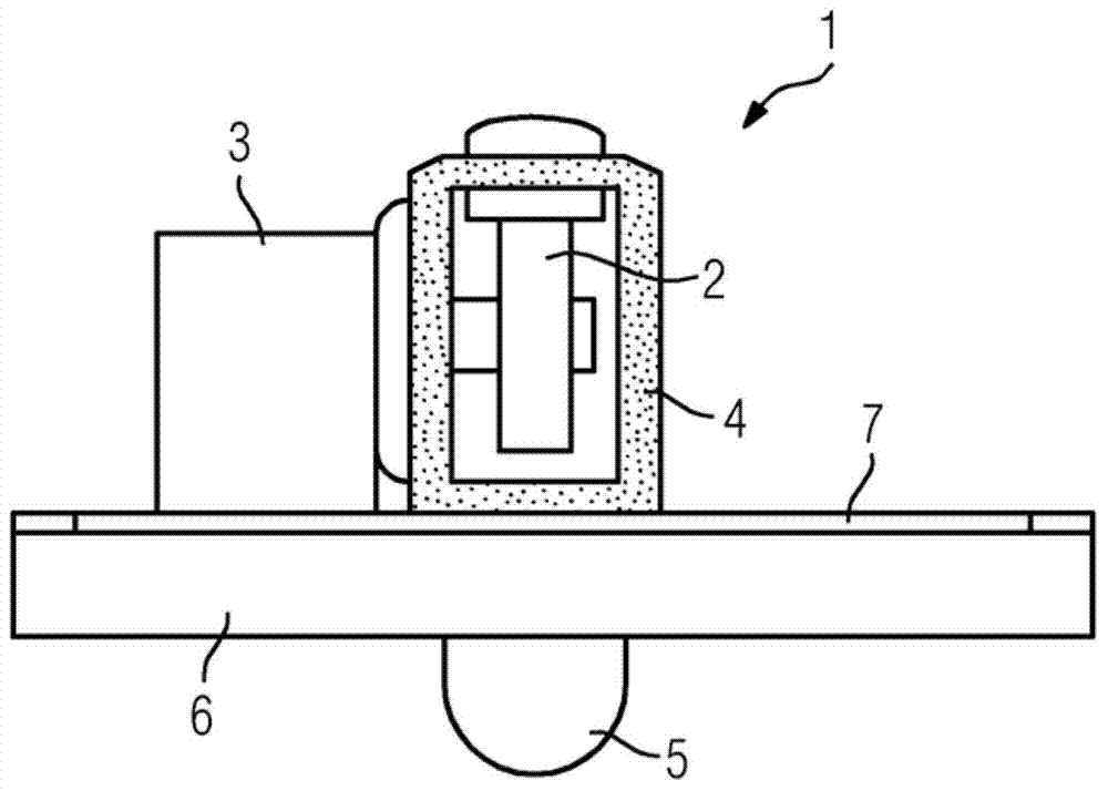
[0025] figure 1 A grinding device 1 according to one embodiment of the invention is shown. The grinding device 1 comprises a grinding disc 2 which is driven in rotation via a drive 3 . The grinding disk 2 is surrounded annularly by a shielding device, which is here formed by a brush device 4 . The brush device 4 comprises a plurality of flexible bristles which protrude beyond the grinding disc 2 so that during normal operation of the grinding device 1 they come into contact with the workpiece to be machined. Furthermore, the grinding device 1 comprises a suction device 5 arranged below the grinding disc 2 , which removes the grinding particles from the shaded processing area of ​​the grinding device 1 during normal operation of the grinding device 1 . The masked processing area is limited by the brush device 4 . The drive of the grinding disc 2 and the suction device 5 are coupled to each other such that the drive is automatically disconnected in the event of a failure of t...


PUM


Abstract

The invention relates to a method and a device for setting a predetermined radial gap width for rotor blades arranged in a housing of a turbomachine in site.

Description

technical field [0001] The invention relates to a method for setting a predetermined amount of radial play of rotor blades arranged in a housing of a fluid machine. Background technique [0002] Blades of fluid machines, in particular turbine blades, are exposed to very high material stresses and correspondingly high wear during operation. For this reason, the blades are replaced by new blades during maintenance work, usually after a predetermined duration of operation. In this case, the operating duration is advantageously selected such that the replaced blade can still be repaired. [0003] If the blades of the turbine are replaced, the turbine rotor blades, turbine guide vanes and guide segments are replaced. In order to be able to ensure that the original turbine performance is maintained during such a replacement, the original radial blade clearance must also be realized in the new turbine rotor blades. For this purpose, the blade tips of the new rotor blades are mac...

Claims


Application Information

Patent Timeline
Patent Type & Authority Applications(China)
IPC IPC(8): B24B19/14B24B55/06
CPCB24B19/14B24B55/06F01D5/005F01D5/20F01D25/26B24B49/00
Inventor 罗尔夫·格罗佩迈克尔·凯勒乌韦·基希许贝尔罗尔夫-迪特尔·沃伊切克
Owner SIEMENS ENERGY GLOBAL GMBH & CO KG
Learn More