Steering vector estimation for minimum variance distortionless response (MVDR) beamforming circuits, systems, and methods

a beamforming circuit and vector estimation technology, applied in the field of microphone arrays, can solve problems such as ambient nois

Active Publication Date: 2016-06-30
STMICROELECTRONICS ASIA PACIFIC PTE
View PDF0 Cites 22 Cited by
  • Summary
  • Abstract
  • Description
  • Claims
  • Application Information

AI Technical Summary

Problems solved by technology

This ambient noise may simply be unwanted sound signals from a different direction that are also p

Method used


Image

  • Steering vector estimation for minimum variance distortionless response (MVDR) beamforming circuits, systems, and methods
  • Steering vector estimation for minimum variance distortionless response (MVDR) beamforming circuits, systems, and methods
  • Steering vector estimation for minimum variance distortionless response (MVDR) beamforming circuits, systems, and methods

Examples


Embodiment Construction

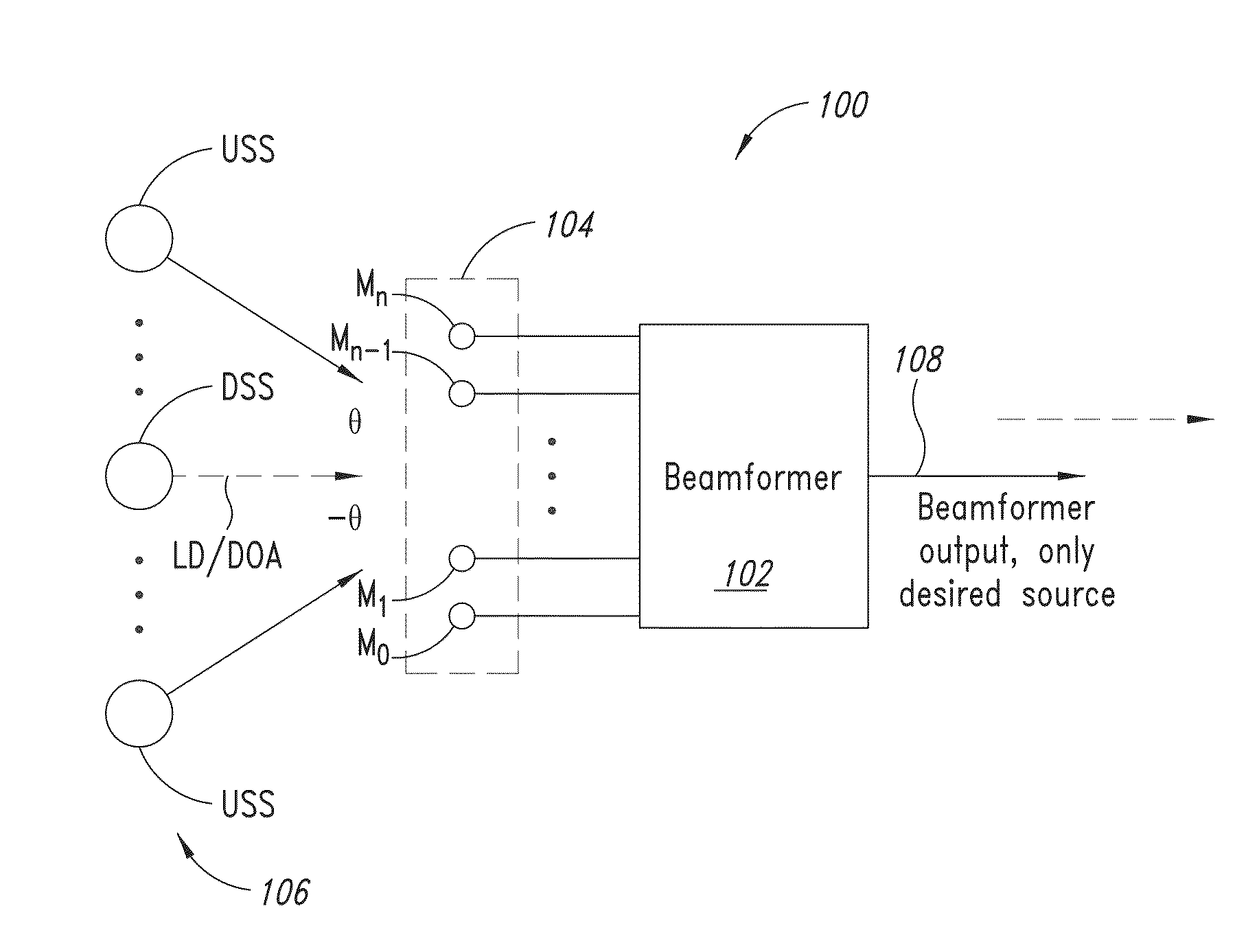
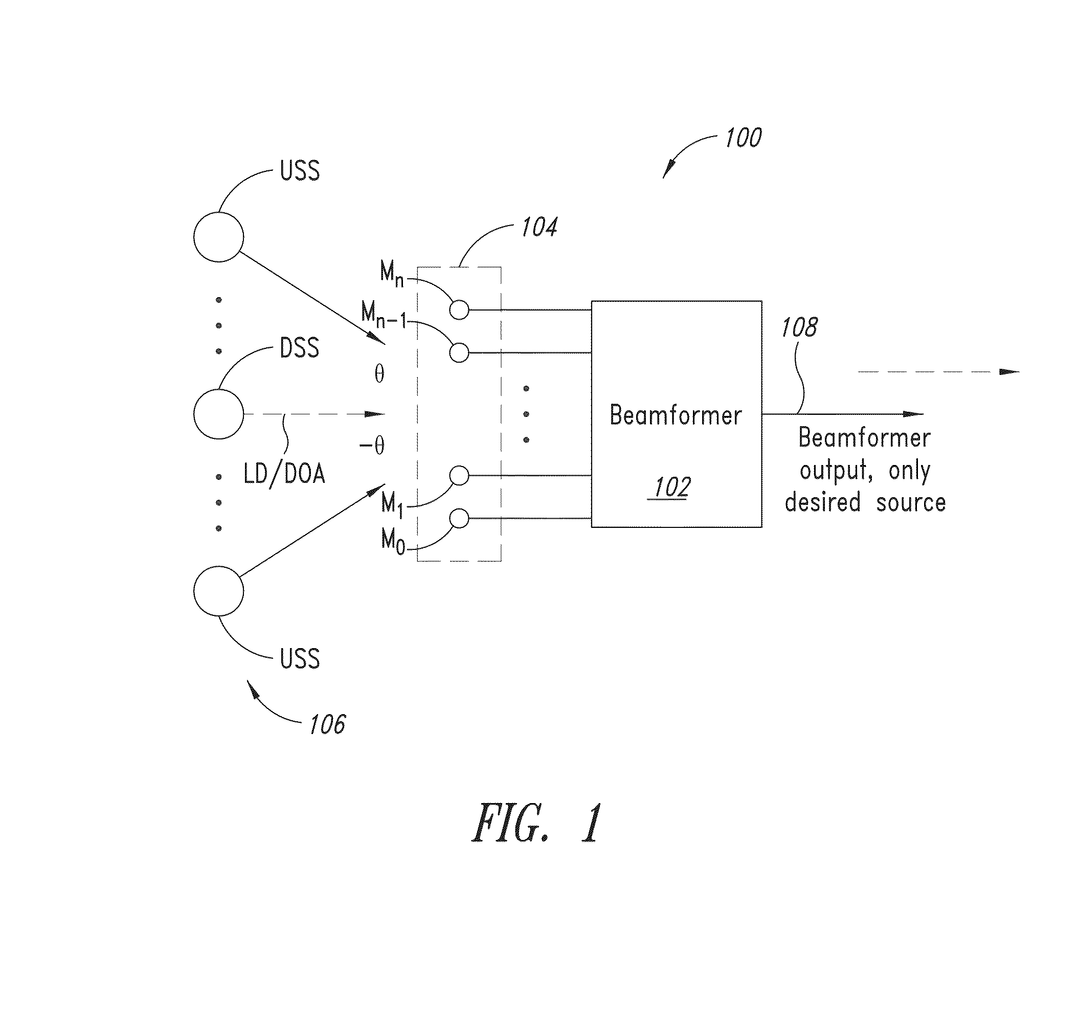
[0011]FIG. 1 is functional diagram illustrating a typical beamforming system 100 in which a beamformer circuit 102 processes audio signals generated by a number of microphones M0-Mn of a microphone array 104 in response to sound waves or signals from a number of sound sources 106 to thereby estimate a steering vector d(f) of the array, as will be described in more detail below. The beamformer circuit 102 processes the signals from the microphone array 104 to generate an output signal 108 indicating the sound captured or received by the array from a desired sound source DSS (i.e., from a sound source in a direction relative to the array defined by the steering vector d(f) of the array), where the desired sound source is one of the number of sound sources 106. In this way, the beamforming circuit 102 effectively spatially filters sound received by the array 104 from undesired sound sources USS among the number of sound sources 106, as will be appreciated by those skilled in the art. I...


PUM


Abstract

A method of estimating a steering vector of a sensor array of M sensors according to one embodiment of the present disclosure includes estimating a steering vector of a noise source located at an angle 0 degrees from a look direction of the array using a least squares estimate of the gains of the sensors in the array, defining a steering vector of a desired sound source in the look direction of the array, and estimating the steering vector by performing element-by-element multiplication of the estimated noise vector and the complex conjugate of steering vector of the desired sound source. The sensors may be microphones.

Description

BACKGROUND[0001]1. Technical Field[0002]The present application is directed generally to microphone arrays, and more specifically to better estimating a steering vector in microphone arrays utilizing minimum variance distortionless response (MVDR) beamforming where mismatches exist among the microphones forming the array.[0003]2. Description of the Related Art[0004]In today's global business environment, situations often arise where projects are assigned to team members located in different time zones and even different countries throughout the world. These team members may be employees of a company, outside consultants, other companies, or any combination of these. As a result, a need arises for a convenient and efficient way for these distributed team members to work together on the assigned project. To accommodate these distributed team situations and other situations where geographically separated parties need to communicate, multimedia rooms have been developed to accommodate m...

Claims


Application Information

Patent Timeline
IPC IPC(8): H04R1/40
CPCH04R2201/40H04R1/406H04R3/005H04R2201/401H04R2201/403H04R2430/23H04R2430/25H04R2499/11H04R2499/13
Inventor NG, SAMUEL SAMSUDINGEORGE, SAPNAMURALIDHAR, KARTHIK
Owner STMICROELECTRONICS ASIA PACIFIC PTE
Why Eureka
Try Eureka