Vehicle travelling control device

a control device and vehicle technology, applied in the direction of process and machine control, distance measurement, instruments, etc., to achieve the effect of reducing the possibility of collision with the preceding vehicl

Active Publication Date: 2016-07-07
TOYOTA JIDOSHA KK
View PDF9 Cites 12 Cited by
  • Summary
  • Abstract
  • Description
  • Claims
  • Application Information

AI Technical Summary

Benefits of technology

[0005]In the related technology described above, by decelerating a vehicle when the position of the preceding vehicle is lost as described above, it can be achieved that the distance to the preceding vehicle is maintained and the possibility of a collision with the preceding vehicle can be decreased. However, in this case, since the vehicle is decelerated when the preceding vehicle is lost, it may cause traffic congestion, and thus, there is room for improvement in this respect.

Problems solved by technology

However, in this case, since the vehicle is decelerated when the preceding vehicle is lost, it may cause traffic congestion, and thus, there is room for improvement in this respect.

Method used


Image

  • Vehicle travelling control device
  • Vehicle travelling control device
  • Vehicle travelling control device

Examples


first embodiment

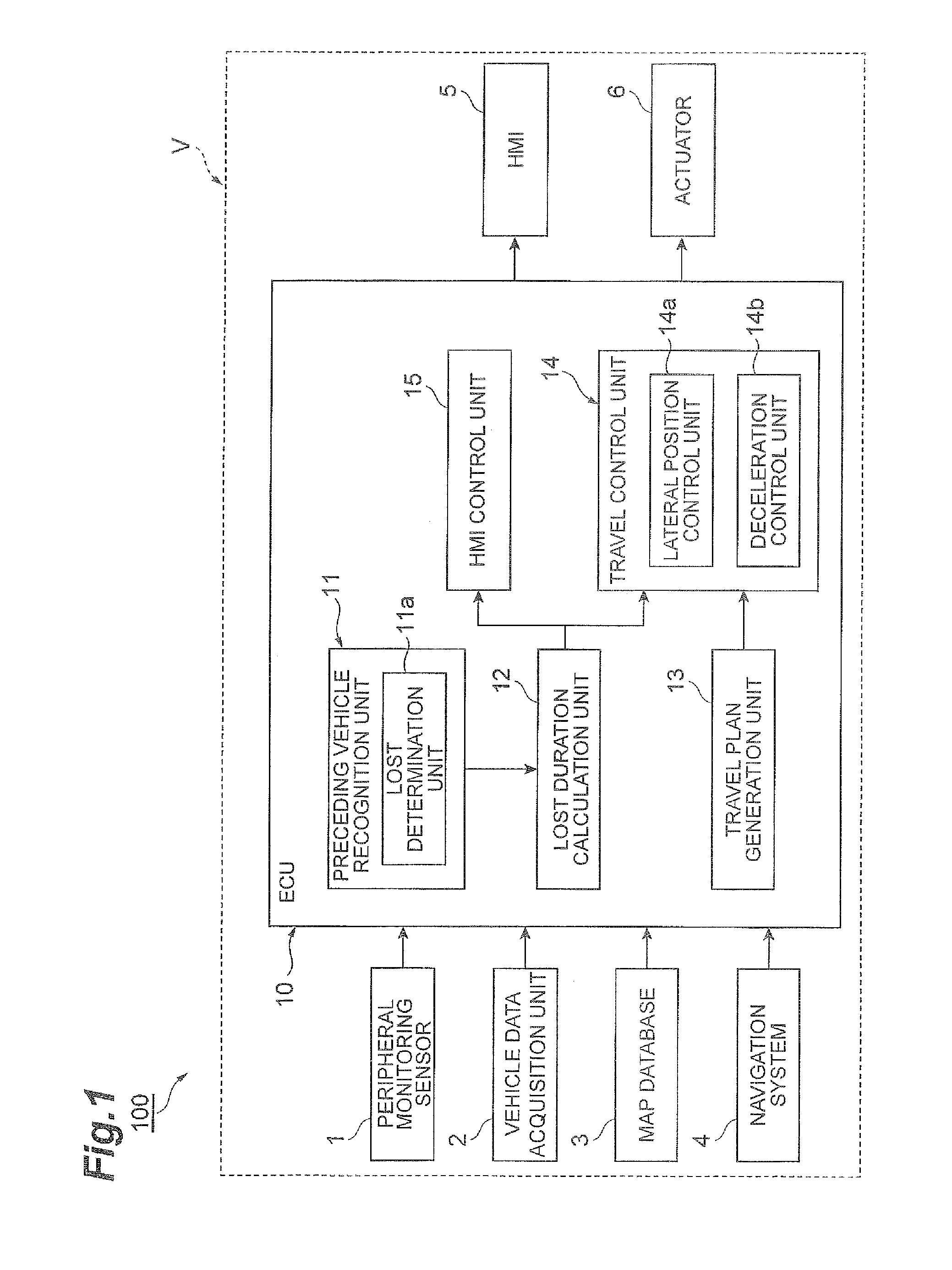
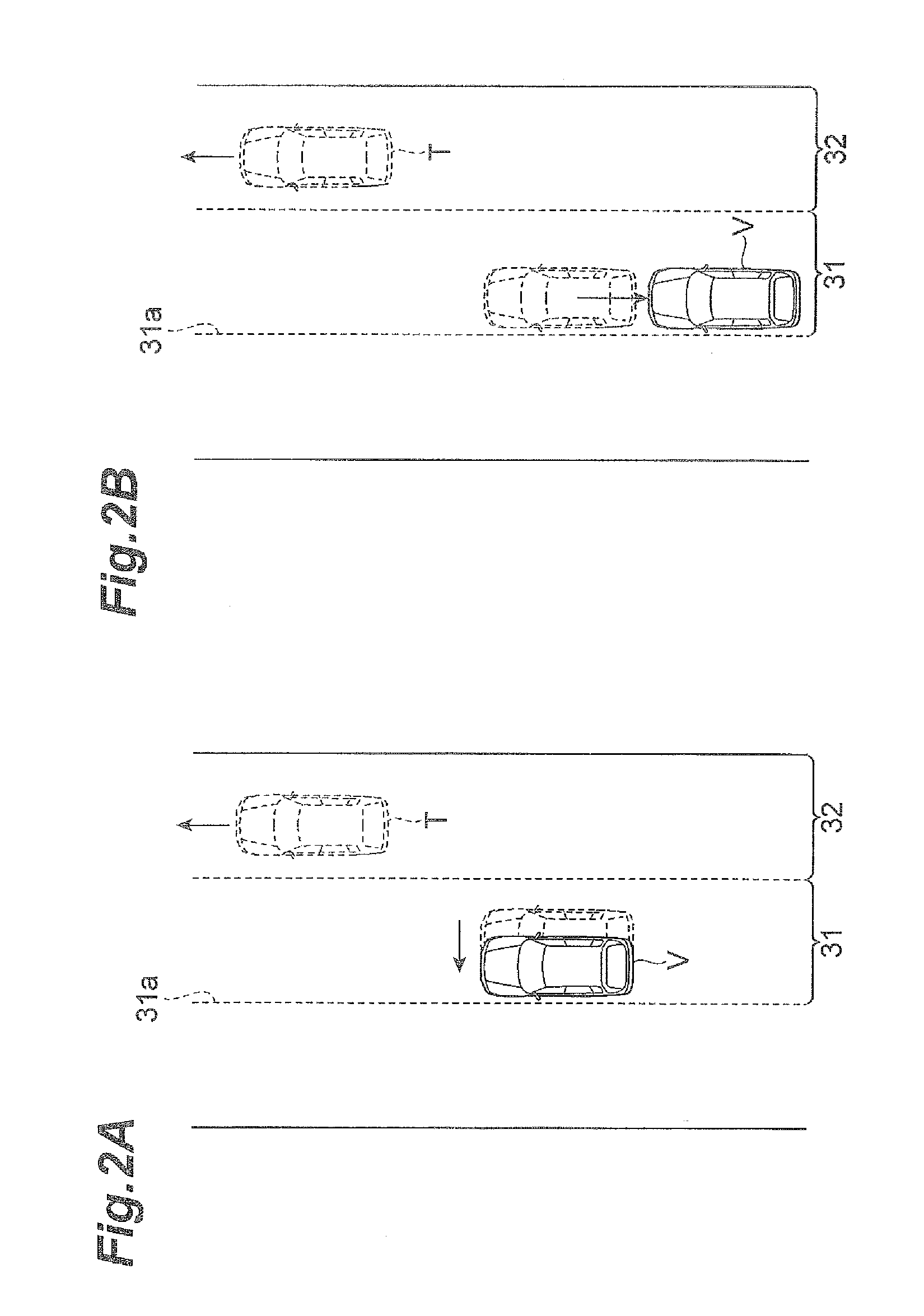
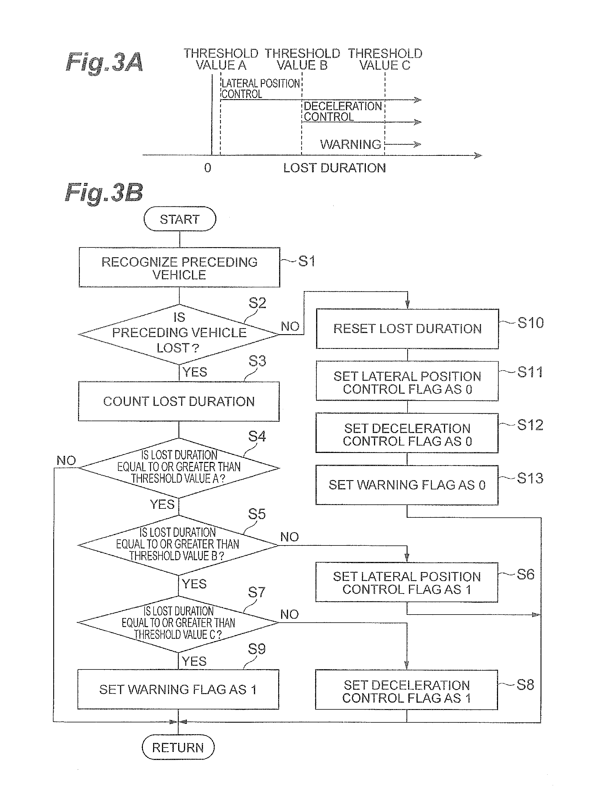
[0019]FIG. 1 is a block diagram illustrating a configuration of a vehicle travelling control device 100. FIG. 2A is an overhead view explaining a lateral position control of the vehicle travelling control device 100. FIG. 2B is an overhead view explaining a deceleration in the vehicle travelling control device 100. FIG. 3A is a diagram explaining a threshold value of the vehicle travelling control device 100.

[0020]As illustrated in FIG. 1, FIG. 2A, and FIG. 2B, the vehicle travelling control device 100 is mounted on a vehicle V such as a vehicle. The vehicle travelling control device 100 causes the vehicle V to automatically travel (automatic driving) on the travelling lane 31 on which the vehicle V travels. The vehicle travelling control device 100 includes a peripheral monitoring sensor (peripheral information detection unit) 1, a vehicle data acquisition unit 2, a map database 3, a navigation system 4, a human machine interface (HMI) 5, an actuator 6, and an electronic control un...

second embodiment

[0072]Next, a second embodiment will be described. In the description in the present embodiment, a point different from the first embodiment will be described.

[0073]FIG. 6 is a block diagram illustrating a configuration of a vehicle travelling control device 200. FIG. 7 is an overhead view explaining the vehicle travelling control device 200. FIG. 8 is a flowchart illustrating processing in the ECU 10 of the vehicle travelling control device 200. As illustrated in FIG. 6, the vehicle travelling control device 200 in the present embodiment is different from the vehicle travelling control device 100 in the first embodiment in a point that the preceding vehicle recognition unit 11 further includes a lost preceding vehicle selection unit lib.

[0074]As illustrated in FIG. 6 and FIG. 7, the preceding vehicle recognition unit 11 recognizes the position, the vehicle speed, and the acceleration of a plurality of preceding vehicles T traveling on at least any one of the adjacent lane 32 and an...


PUM


Abstract

A vehicle travelling control device is configured to cause a vehicle to automatically travel along the target lateral position set in a travelling lane in advance. The device includes a peripheral information detection unit configured to detect peripheral information of the vehicle, a preceding vehicle recognition unit configured to recognize a position of the preceding vehicle in an adjacent lane which is adjacent to the travelling lane based on the peripheral information detection unit, and a travel control unit configured to cause the vehicle to automatically travel along a separated lateral position which is separated from the target lateral position at the opposite side of the adjacent lane side in a case where a lost duration that is a continuous period of time during which the position of the preceding vehicle is lost in the preceding vehicle recognition unit reaches a first predetermined time.

Description

BACKGROUND OF THE INVENTION[0001]1. Field of the Invention[0002]The present invention relates to a vehicle travelling control device.[0003]2. Related Background Art[0004]As a technology relating to a vehicle travelling control device in the related art, as disclosed in Japanese Unexamined Patent Application Publication No. 2006-44591, a deceleration control device is known, in which it is determined whether or not a preceding vehicle is lost (a driver loses sight of the preceding vehicle), and when it is determined that the preceding vehicle is lost, then, causes a vehicle to decelerate.SUMMARY[0005]In the related technology described above, by decelerating a vehicle when the position of the preceding vehicle is lost as described above, it can be achieved that the distance to the preceding vehicle is maintained and the possibility of a collision with the preceding vehicle can be decreased. However, in this case, since the vehicle is decelerated when the preceding vehicle is lost, it...

Claims


Application Information

Patent Timeline
Patent Type & Authority Applications(United States)
IPC IPC(8): B60W30/16B60W10/20B60W10/18B60W10/04G05D1/00B60W10/30
CPCB60W30/16G05D1/0088B60W10/30B60W10/18B60W10/04B60W2710/30B60W2550/308B60W2550/302B60W2720/10B60W2710/18B60W2710/20B60W10/20B60W2554/801B60W2556/50B60W2554/00B60W50/14B60W30/12B60W2554/804B60W2554/4041B60W60/0059B60W60/0053
Inventor TORII, HARUTOHASHIMOTO, RYUTATAIRA, TETSUYA
Owner TOYOTA JIDOSHA KK
Why Eureka
Try Eureka