Computational bluetooth tag with backscatter

Active Publication Date: 2016-07-07
RICOH KK
View PDF1 Cites 21 Cited by
  • Summary
  • Abstract
  • Description
  • Claims
  • Application Information

AI Technical Summary

Benefits of technology

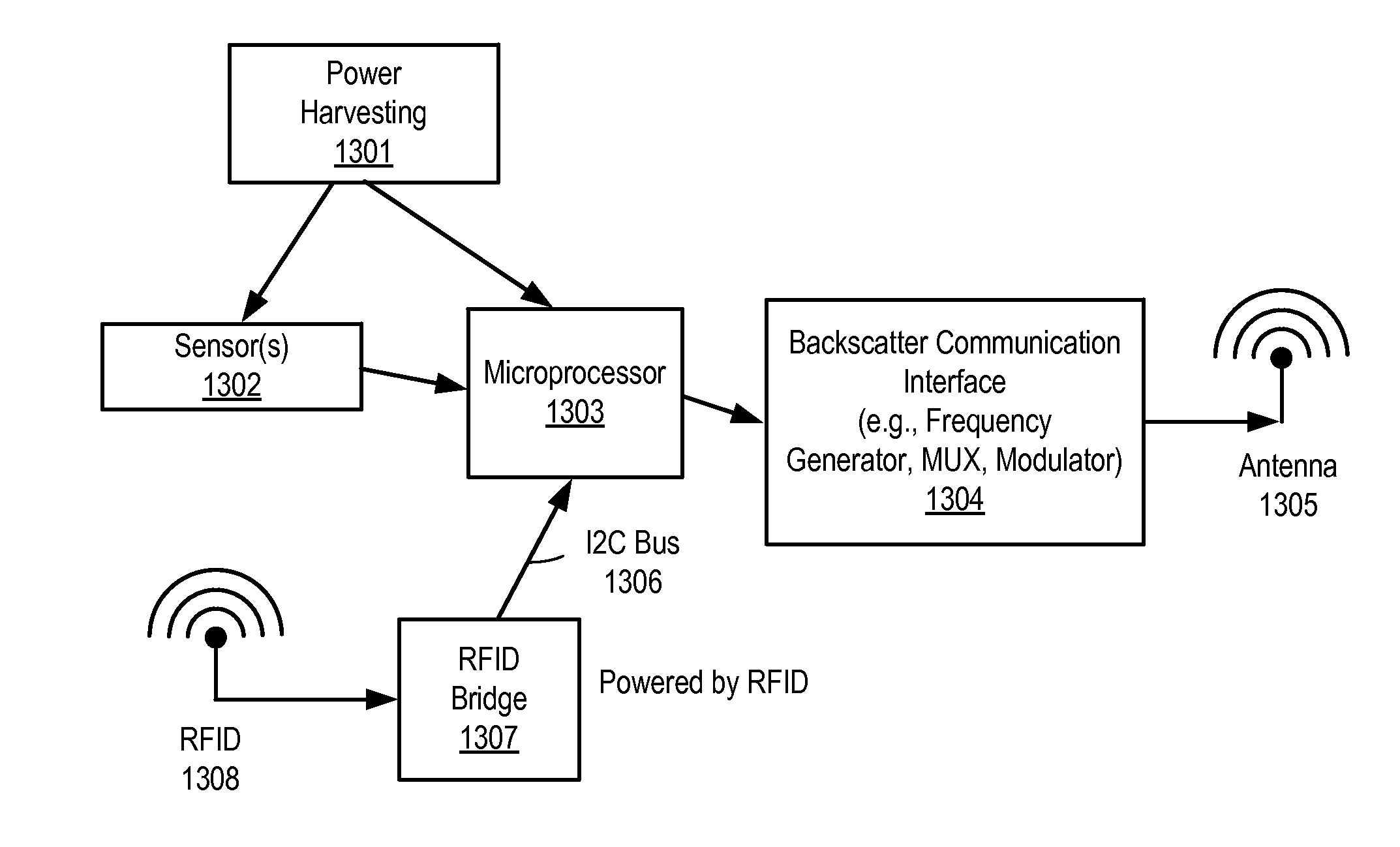
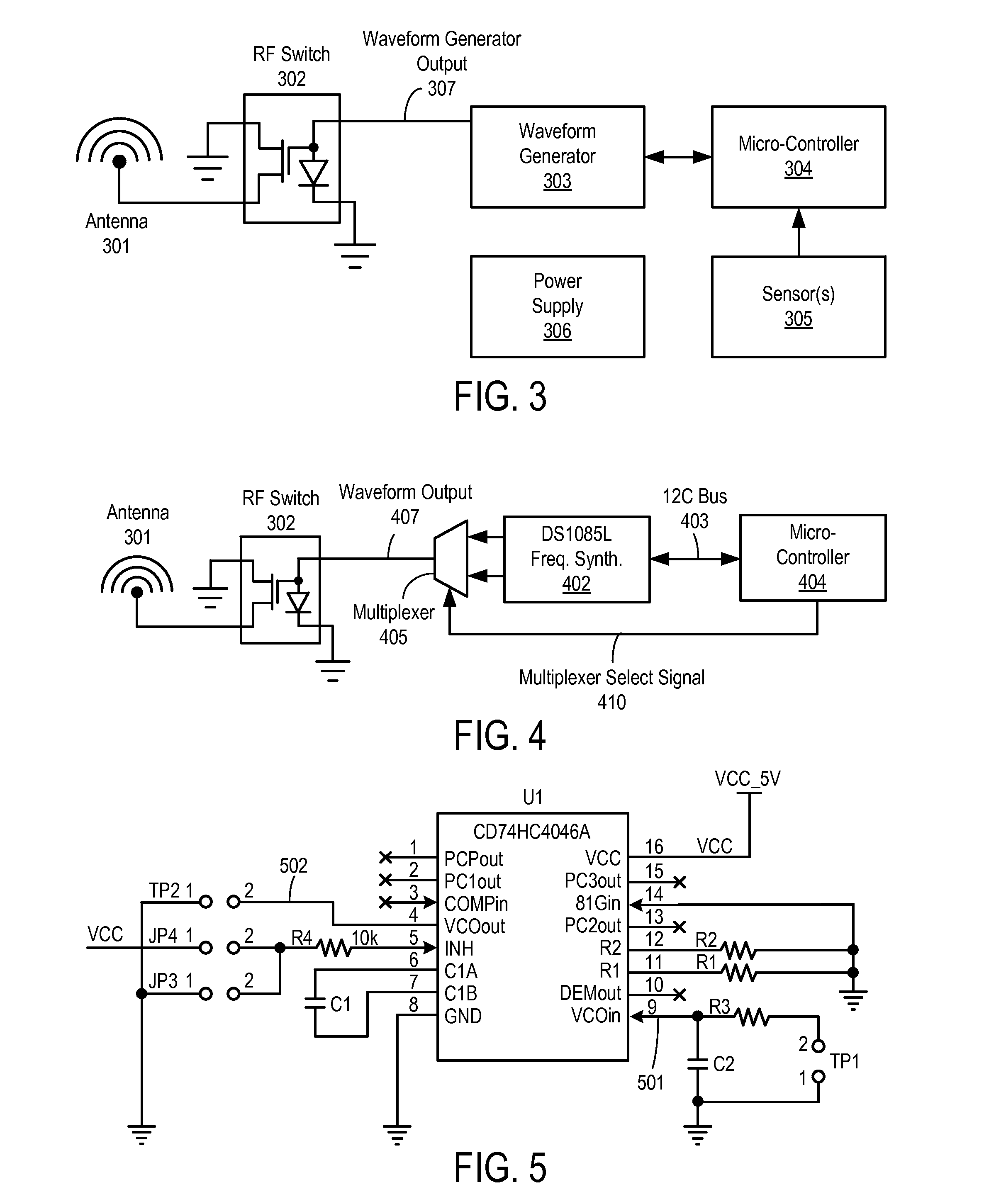
[0013]A backscatter modulation radio-frequency (RF) sensor and method for using the same are disclosed herein. In one embodiment, the RF sensor comprises: an energy harvesting unit operable to convert incident RF energy to direct current (DC); a storage unit operable to store recovered DC power; one or more sensors for sensing; a backscatter communication interface to backscatter energy to communicate one or more packets using frequency-shift keying (FSK) modulation, wherein the backscatter communication interface comprises a frequency synthesizer, a multiplexer, and a RF switch, and f

Problems solved by technology

Radio Frequency Identification (RFID) has existed for several decades now, and has experie

Method used


Image

  • Computational bluetooth tag with backscatter
  • Computational bluetooth tag with backscatter
  • Computational bluetooth tag with backscatter

Examples


Embodiment Construction

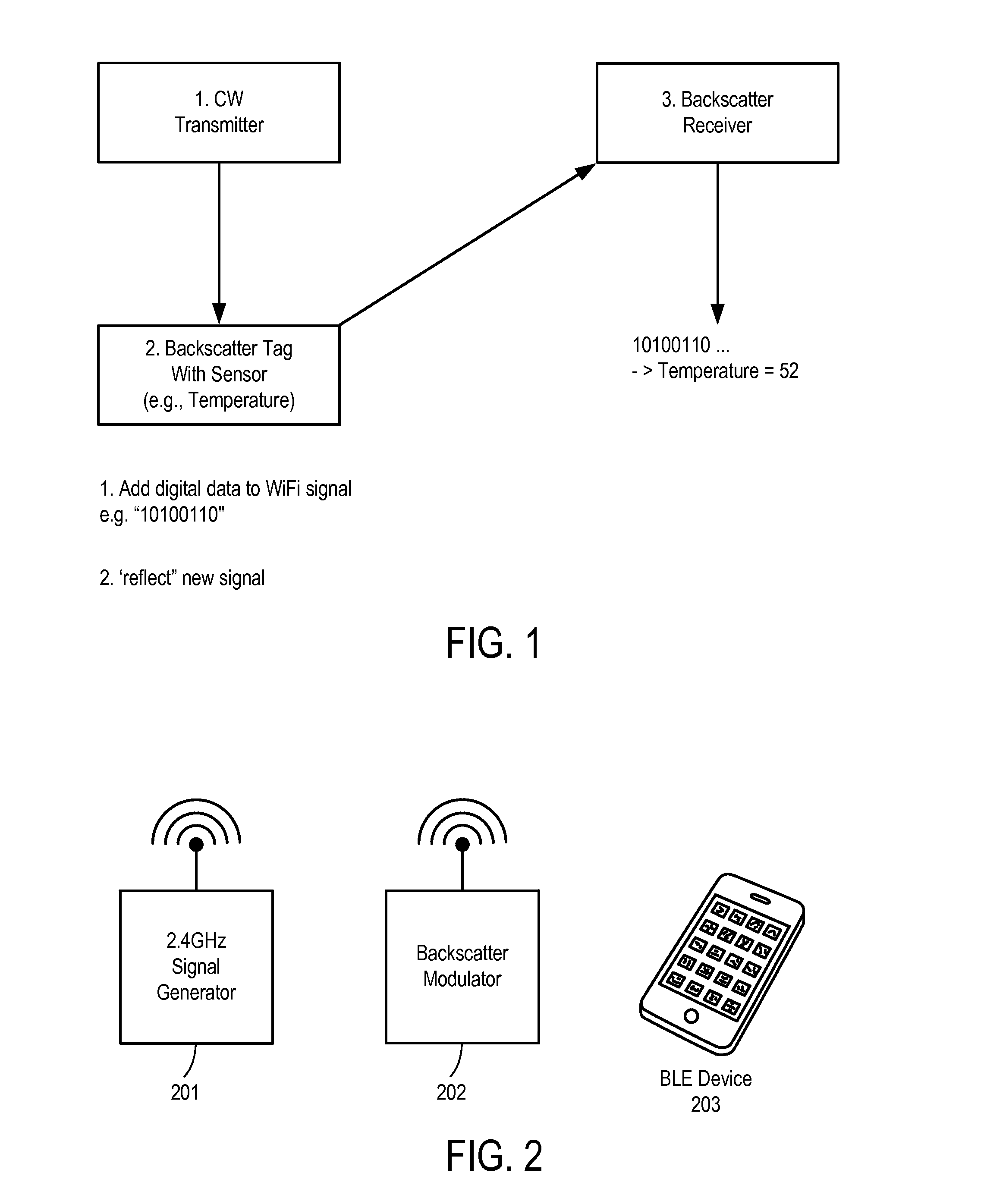
[0041]A new method and apparatus for transmitting Bluetooth packets using backscatter communications is described. This communication technique enables ultra-low-power sensor tags, by reducing the energy required to communicate in some embodiments by a factor of 1000.

[0042]The disclosure that follows describes practical system implementations for modulated backscatter devices, including generation of the signals as well as overcoming multi-tag and configuration issues.

[0043]In the following description, numerous details are set forth to provide a more thorough explanation of the present invention. It will be apparent, however, to one skilled in the art, that the present invention may be practiced without these specific details. In other instances, well-known structures and devices are shown in block diagram form, rather than in detail, in order to avoid obscuring the present invention.

[0044]Some portions of the detailed descriptions which follow are presented in terms of algorithms ...


PUM


Abstract

A backscatter modulation radio-frequency (RF) sensor and method for using the same are disclosed herein. In one embodiment, the RF sensor comprises: an energy harvesting unit operable to convert incident RF energy to direct current (DC); a storage unit operable to store recovered DC power; one or more sensors for sensing; a backscatter communication interface to backscatter energy to communicate one or more packets using a frequency-shift keying (FSK) modulator; and a microcontroller coupled to the energy harvesting and storage units, the one or more sensors, and the backscatter communicator, the microcontroller operable to cause the backscatter communication interface to communicate sensed data from at least one of the one or more sensors while powered by energy previously harvested and stored by the energy harvesting and storage unit.

Description

PRIORITY[0001]The present patent application claims priority to and incorporates by reference the corresponding provisional patent application Ser. No. 62 / 099,357, titled, “Computation Bluetooth with Backscatter,” filed on Jan. 2, 2015.FIELD OF THE INVENTION[0002]Embodiments of the present invention relate to the field of radio-frequency (RF) communication; more particularly, embodiments of the present invention relate to devices that perform RF energy harvesting.BACKGROUND OF THE INVENTION[0003]Radio Frequency Identification (RFID) has existed for several decades now, and has experienced many different standards, applications, and interoperability and compatibility issues. However, the RFID EPC Gen2 standard, introduced in 2004, has become a unified standard across the industry.[0004]RFID uses modulated backscatter. Modulated backscatter is a technique where a continuous wave radio frequency signal is essentially turned on and off (modulated) and reflected back to the receiver. The...

Claims


Application Information

Patent Timeline
IPC IPC(8): G06K7/10H04B5/00
CPCH04B5/0062G06K7/10158H03L7/0995H04B5/0031H04B7/0617
Inventor GUDAN, KENNETHHULL, JONATHAN J.
Owner RICOH KK
Why Eureka
Try Eureka