Current detector and power conversion device

a current detector and power conversion technology, applied in the direction of electric devices, thermoelectric instruments, instruments, etc., can solve the problems of increasing the error of the current detection value, the inability to achieve a fixed value, and the inability to resist r, so as to improve the accuracy of the current detection

Inactive Publication Date: 2016-07-07
FUJI ELECTRIC CO LTD
View PDF10 Cites 12 Cited by
  • Summary
  • Abstract
  • Description
  • Claims
  • Application Information

AI Technical Summary

Benefits of technology

[0028]According to the invention, when the current detector measures the main circuit current flowing through the inductor based on a voltage drop, temperature of the inductor's main winding is taken into account to avoid an error that would otherwise occur if a resistance of the main winding were assumed to have a fixed value, thereby significantly improving the accuracy of the current detection.

Problems solved by technology

For example, when the temperature rises by 80[K], the winding resistance R becomes as high as 1.3 times, meaning that the heretofore known technology of JP-A-3-178555 on the premise that the winding resistance R is a fixed value is not practical because the margin of error of the current detection value increases significantly.

Method used


Image

  • Current detector and power conversion device
  • Current detector and power conversion device
  • Current detector and power conversion device

Examples


first embodiment

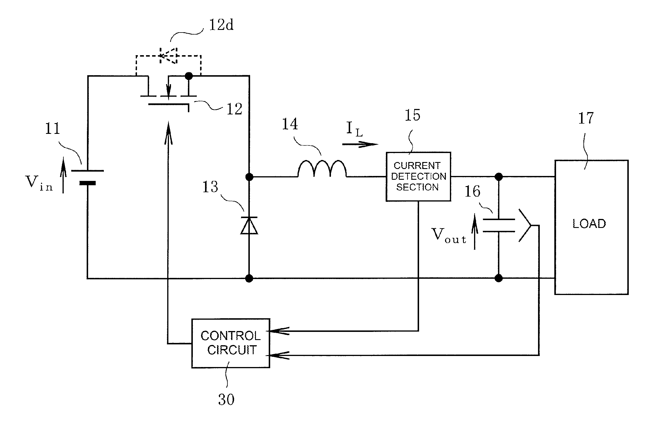
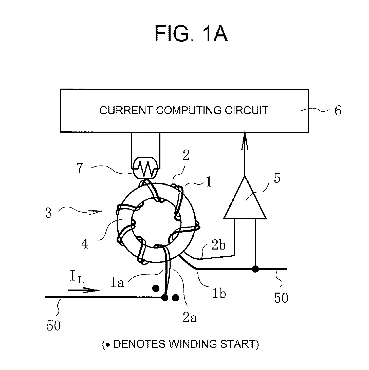
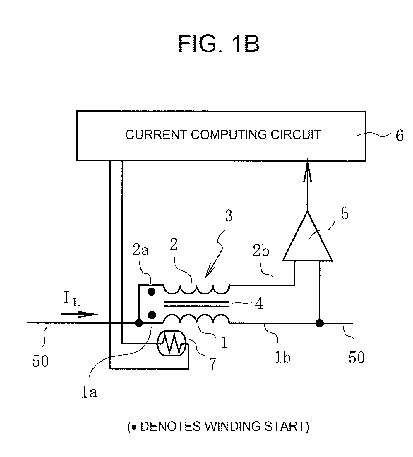
[0037]Firstly, FIG. 1A is a configuration diagram of a current detector according to the invention, and FIG. 1B is a circuit diagram thereof. The current detector is connected between the output terminal of a semiconductor switching element 12 and one end of a smoothing capacitor 16, for example, as shown in FIG. 5, and is used to detect a current (a main circuit current) IL flowing through an inductor, switch the semiconductor switching element 12 with a control circuit 30, and control an output voltage Vout in accordance with a command value.

[0038]In FIGS. 1A and 1B, a main winding 1 and an auxiliary winding 2, which are equal in the number of turns, are wound in the same direction on a core 4 of an inductor 3. One ends 1a and 2a of the main winding 1 and auxiliary winding 2, at which winding starts, are connected to a main circuit line 50, and the main circuit line 50 is connected to the output side of a power conversion device, as shown in FIG. 5. Also, the other ends 1b and 2b ...

second embodiment

[0056]Next, FIG. 4 is a circuit diagram showing the invention. In FIG. 4, the same signs are given to component portions the same as those of FIGS. 1A, 1B, and 3, and hereafter, a description will be given centering on the differences.

[0057]In the first embodiment, the altered inductors 3 and 3A are used, but in the second embodiment, the need to alter the inductor itself is eliminated.

[0058]That is, in FIG. 4, the inductor connected in series to the main circuit line 50 is configured of only the main winding 1. Also, 8 is a transformer with a winding turn ratio of 1:1, wherein a primary winding 8A of the transformer 8 is connected in parallel to the main winding 1. Furthermore, one end of a secondary winding 8B is connected to the one end of the main winding 1, and the other end of the secondary winding 8B is connected to one input terminal of the voltage detection section 5. The other end of the main winding 1 is connected to the other input terminal of the voltage detection secti...


PUM


Abstract

A current detector for detecting a main circuit current of an inductor connected to a switching element whose operation generates that current. The inductor includes main and auxiliary windings equal in numbers of turns and connected to the detector so as to cancel out electromotive forces generated by the operation in the windings. The detector includes a voltage detection unit having two input terminals. One end of each winding is connected to a different one of these terminals. The voltage detection unit detects a voltage difference between the connected ends. The detector also includes a temperature detection unit detecting a temperature of the main winding, and a current calculation unit correcting a main winding resistance using the detected temperature and calculating a current as the main circuit current, using the corrected resistance and an average detected voltage calculated from sampled values of the detected voltage using a sampling frequency.

Description

CROSS-REFERENCE TO RELATED APPLICATION[0001]This is a continuation application of International Application number PCT / JP2014 / 056108, which was filed on Mar. 10, 2014 and designated the United States. The disclosure of this earlier application is incorporated herein by reference.BACKGROUND OF THE INVENTION[0002]1. Technical Field[0003]The present invention relates to a current detector, which detects a current flowing through an inductor, and a power conversion device which carries out power conversion by controlling a semiconductor switching element on / off using a current detection value detected by the current detector.[0004]2. Background Art[0005]As a chopper which boosts or bucks a direct current voltage, there is one which detects a current flowing through an inductor in which to store energy, and controls a semiconductor switching element on / off based on the current detection value of the detected current.[0006]FIG. 5 shows a common buck chopper including the current detection...

Claims


Application Information

Patent Timeline
Patent Type & Authority Applications(United States)
IPC IPC(8): H02M1/08G01R19/00G01R19/32
CPCH02M1/08H02M2001/0009G01R19/0092G01R19/32H02M3/155H02M3/156H02M1/0009G01R15/185
Inventor NEMOTO, YUJIYAMADA, RYUJI
Owner FUJI ELECTRIC CO LTD
Why Eureka
Try Eureka