UAV panoramic imaging

a panoramic imaging and uav technology, applied in the field of uav panoramic imaging, can solve the problems of difficult control of uav, large error margin for civilian use, and several drawbacks of existing approaches, and achieve the effect of reducing the complexity of at least on

Active Publication Date: 2016-07-07
SZ DJI OSMO TECH CO LTD
View PDF4 Cites 102 Cited by
  • Summary
  • Abstract
  • Description
  • Claims
  • Application Information

AI Technical Summary

Benefits of technology

[0008]According to an aspect of the present invention, a system for generating panoramic aerial images is provided. The system comprises a carrier configured to couple with an unmanned aerial vehicle (UAV); an image capturing device configured to couple with the carrier, the carrier configured to permit the image capturing device to rotate around at least two orthogonal axes, the at least two axes comprising a first axis and a second axis; one or more controllers, collectively or individually, configured to cause the carrier to, while the UAV is hovering near a predetermined location, (1) rotate the image capturing device by a predetermined angle of rotation around the first axis, while the image capturing device capture a plurality of successive images at predetermined intervals; and (2) stabilize the image capturing device such that the image capturing device substantially maintains a predetermined spatial disposition with respect to at least the second axis during the rotation of the image capturing device; and one or more processors onboard the UAV, collectively or individually, configured to generate a panoramic image based on the plurality of images.
[0191]According to another aspect of the present invention, a system for generating panoramic aerial images is provided. The system comprises an unmanned aerial vehicle (UAV) configured to hover near a predetermined location and rotate by a predetermined angle around a predetermined axis; and an image capturing device coupled to the UAV via a carrier, wherein the image capturing device is configured to capture a plurality of successive images used for generating a panoramic image while the UAV rotates around the predetermined axis, and carrier is configured to stabilize the image capturing device such that the image capturing device maintains a substantially leveled disposition relative to the ground level while the image capturing device captures the plurality of successive images.

Problems solved by technology

Such existing approaches suffer from several drawbacks.
First, it may be difficult to control the UAV to execute a predetermined flight path.
The margin of error for civilian-use GPS sensors may be at meter level.
Such errors of sensors may cause the UAV to deviate from the predetermined flight path.
Furthermore, manual remote control of the UAV by a user to achieve the predetermined flight path may become difficult when the UAV is far from the user, even if the user is an experienced UAV operator.
The inability of the UAV to precisely execute the predetermined flight path may cause substantial shifts among the captured images, hence making it more difficult to stitch the images together in order to generate the panoramic image.
Second, it is typically difficult to stabilize an image capturing device during the panoramic imaging process using existing approaches.
Furthermore, motions from the UAV (such as vibrations) or disturbances from other sources may cause unintended motions for the image capturing device during the panoramic imaging process, decreasing the quality of the captured images and increasing the complexity of the computation required for generating good-quality panoramic images.
The complexity of the image stitching process can be attributed to the fact that most of the aerial images are captured on a moving and unstabilized platform.
However, offboard processing of the images not only increases the traffic on data communication channels between the UAV and remote devices but also introduces delays between the capture of the images and the generation of the panoramic images.

Method used


Image

  • UAV panoramic imaging
  • UAV panoramic imaging
  • UAV panoramic imaging

Examples


Embodiment Construction

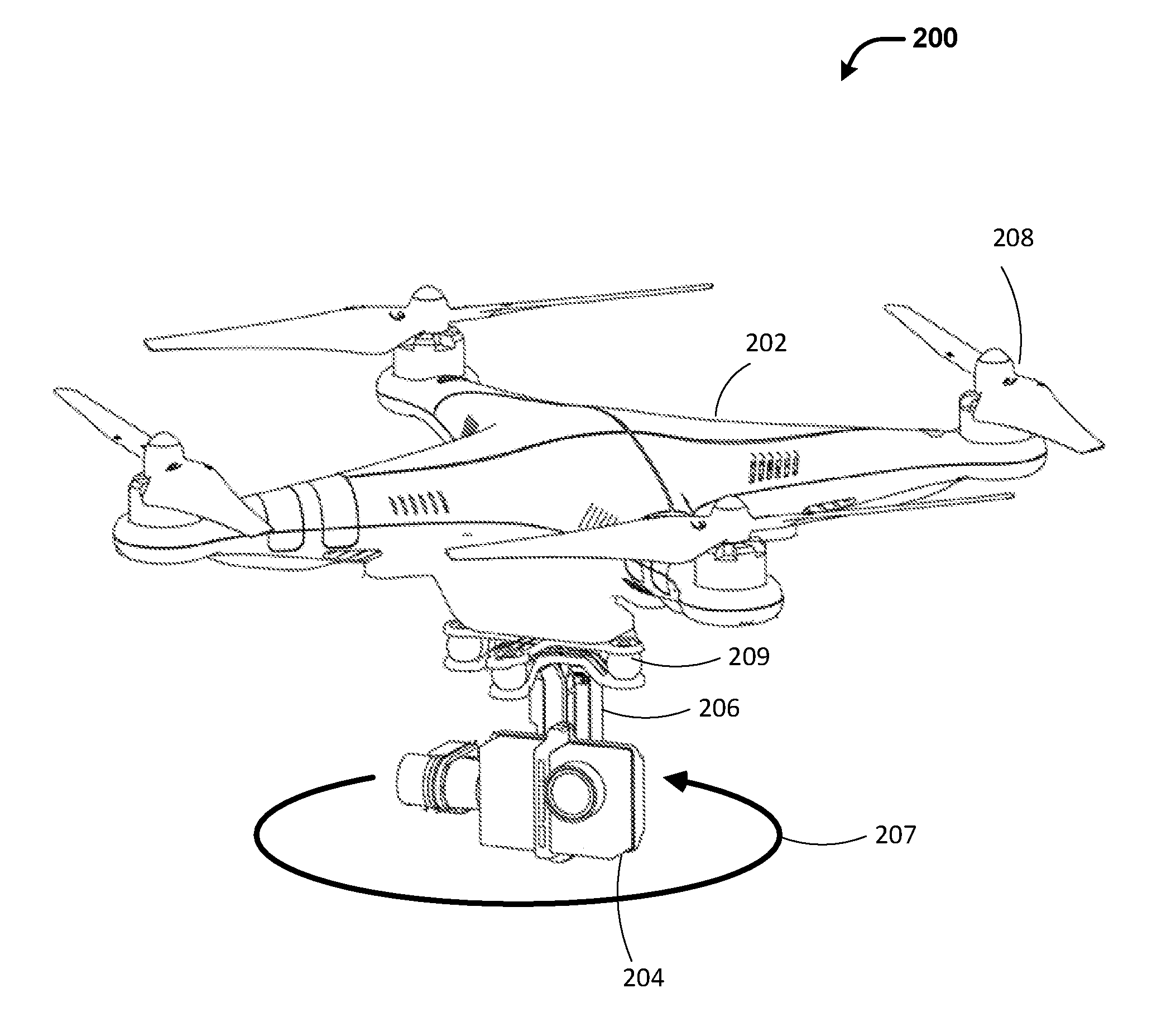
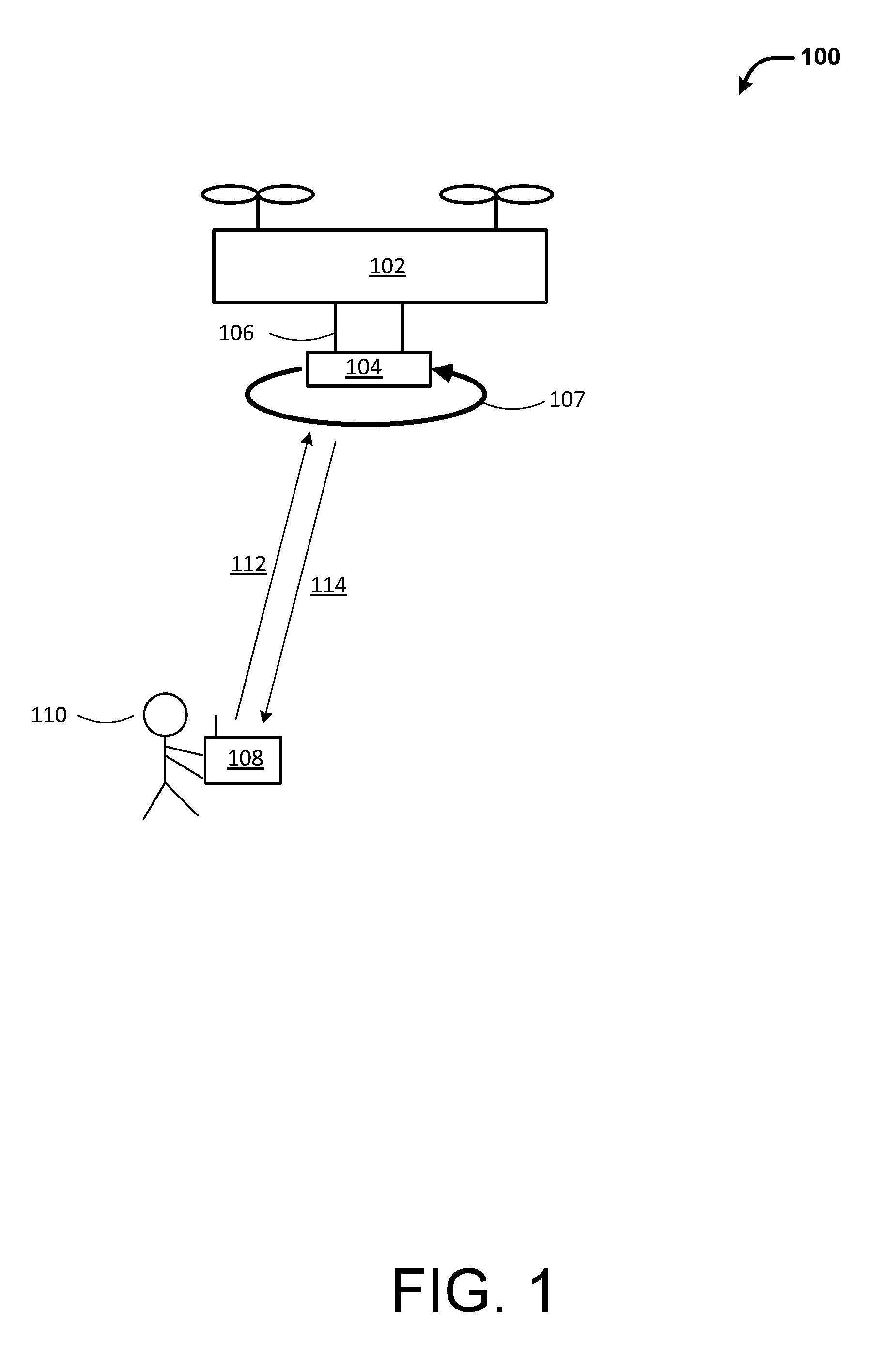
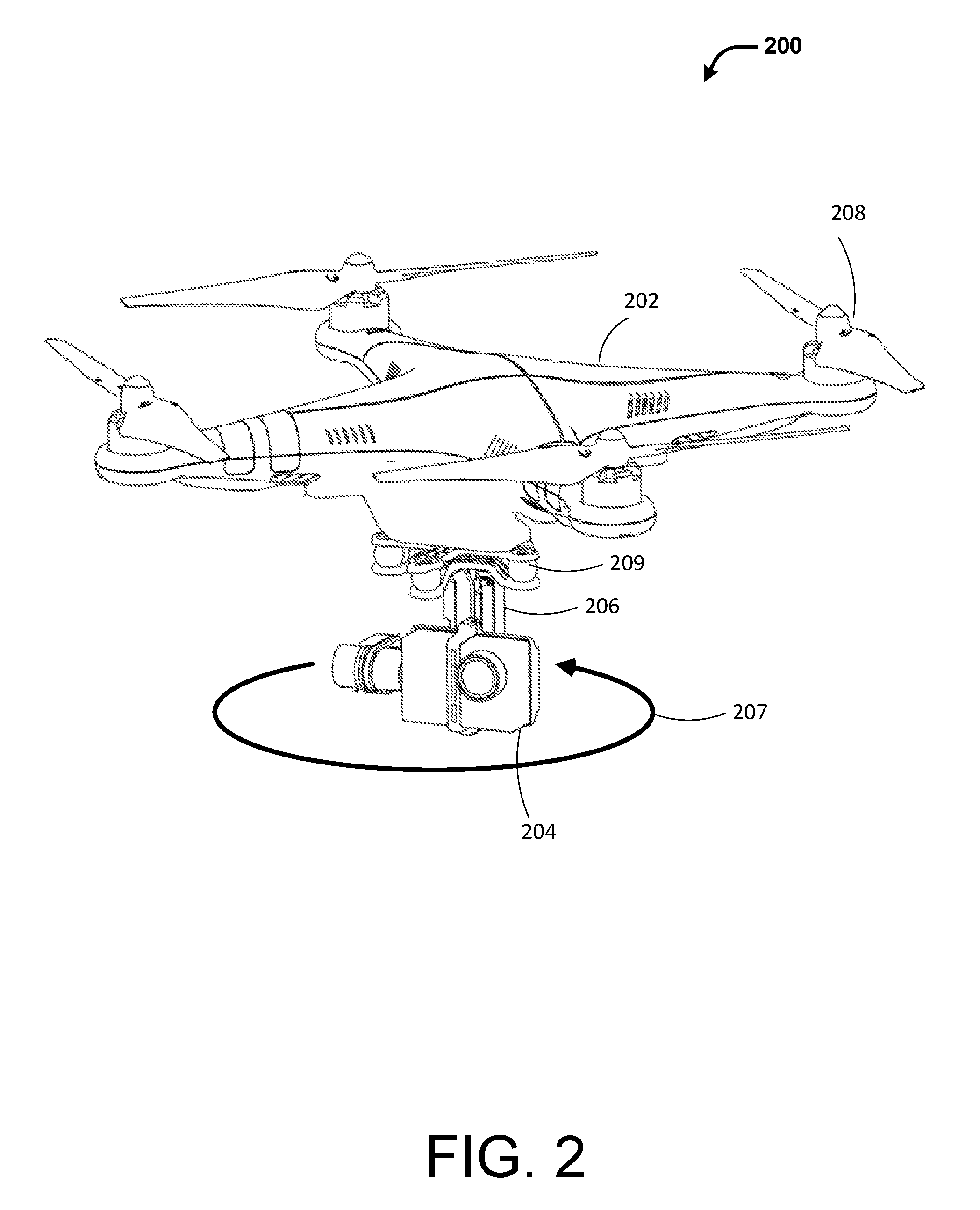
[0216]The present invention provides methods, systems, and apparatus for generating panoramic aerial images that overcome the drawbacks of existing approaches. In particular, an unmanned aerial vehicle (UAV) may maintain a hover position at a desired location when panoramic imaging takes place, instead of executing a predetermined flight path. Maintaining a hover position is typically easier to achieve by a UAV than controlling the UAV to execute a predetermined flight path. An imaging device may be supported on the UAV with aid of a carrier. Furthermore, the carrier may be used to stabilize an image capturing device, and hence its optical axis, as the image capturing device is rotated around a rotational axis to capture a plurality of images, while the UAV hovers at the predetermined location. For example, the carrier may be configured to keep the image capturing device leveled relative to the ground such that the rotation axis for the image capturing device is substantially vertic...


PUM


Abstract

The present invention provides methods, systems, and apparatus for generating panoramic aerial images. An image capturing device is coupled to an unmanned aerial vehicle (UAVs) via a carrier configured to allow the image capturing device to rotate around one, two, or three axes relative to the UAV. To generate a panoramic image, the UAV is brought to hover or remain substantially stationary near a predetermined location. While the UAV is hovering over the predetermined position, the carrier causes the image capturing device to rotate around a first axis while stabilizing the image capturing device with respect to at least a second axis. As the image capturing device rotates, it captures a plurality of overlapping images. The plurality of images can be processed entirely onboard the UAV to generate a panoramic image without transmitting the plurality of images to a remote device.

Description

CROSS-REFERENCE[0001]This application is a continuation of International Application No. PCT / CN2014 / 094711, filed on Dec. 23, 2014. The above-referenced applications are hereby incorporated by reference.BACKGROUND OF THE INVENTION[0002]Aerial vehicles such as unmanned aerial vehicles (UAVs) can be used for performing surveillance, reconnaissance, and exploration tasks for military and civilian applications. Such aerial vehicles may carry a payload configured to perform a specific function, such as capturing images of surrounding environment.[0003]In some instances, it may be desirable to obtain panoramic images based on aerial images captured by a UAV. Existing approaches for generating panoramic aerial images using a UAV typically require the UAV to execute a predetermined flight path as an onboard image capturing device captures multiple images of the surrounding environment. The captured images are then transmitted from the UAV to a ground station or other remote devices, where t...

Claims


Application Information

Patent Timeline
Patent Type & Authority Applications(United States)
IPC IPC(8): H04N5/232B64D47/08B64C39/02H04N5/225
CPCH04N5/23238H04N5/2252B64C2201/127B64C39/024B64D47/08H04N5/77H04N23/682H04N23/685H04N23/698B64U10/13B64U50/19B64U2101/30
Inventor WANG, MINGYUCAO, ZISHENGLIANG, TAIWENYU, LIFU
Owner SZ DJI OSMO TECH CO LTD
Why Eureka
Try Eureka