Sound pickup device, program recorded medium, and method
a sound pickup and program recording technology, applied in the direction of transducer details, electrical transducers, transducer circuits, etc., can solve the problems of musical noise, annoyance of listeners, and unpleasant abnormal sounds, so as to suppress the pickup of background noise components
- Summary
- Abstract
- Description
- Claims
- Application Information
AI Technical Summary
Benefits of technology
Problems solved by technology
Method used
Image
Examples
first exemplary embodiment
(B) Modified Examples of First Exemplary Embodiment
[0092]Detailed description follows regarding modified examples of the first exemplary embodiment described above, with reference to the drawings.
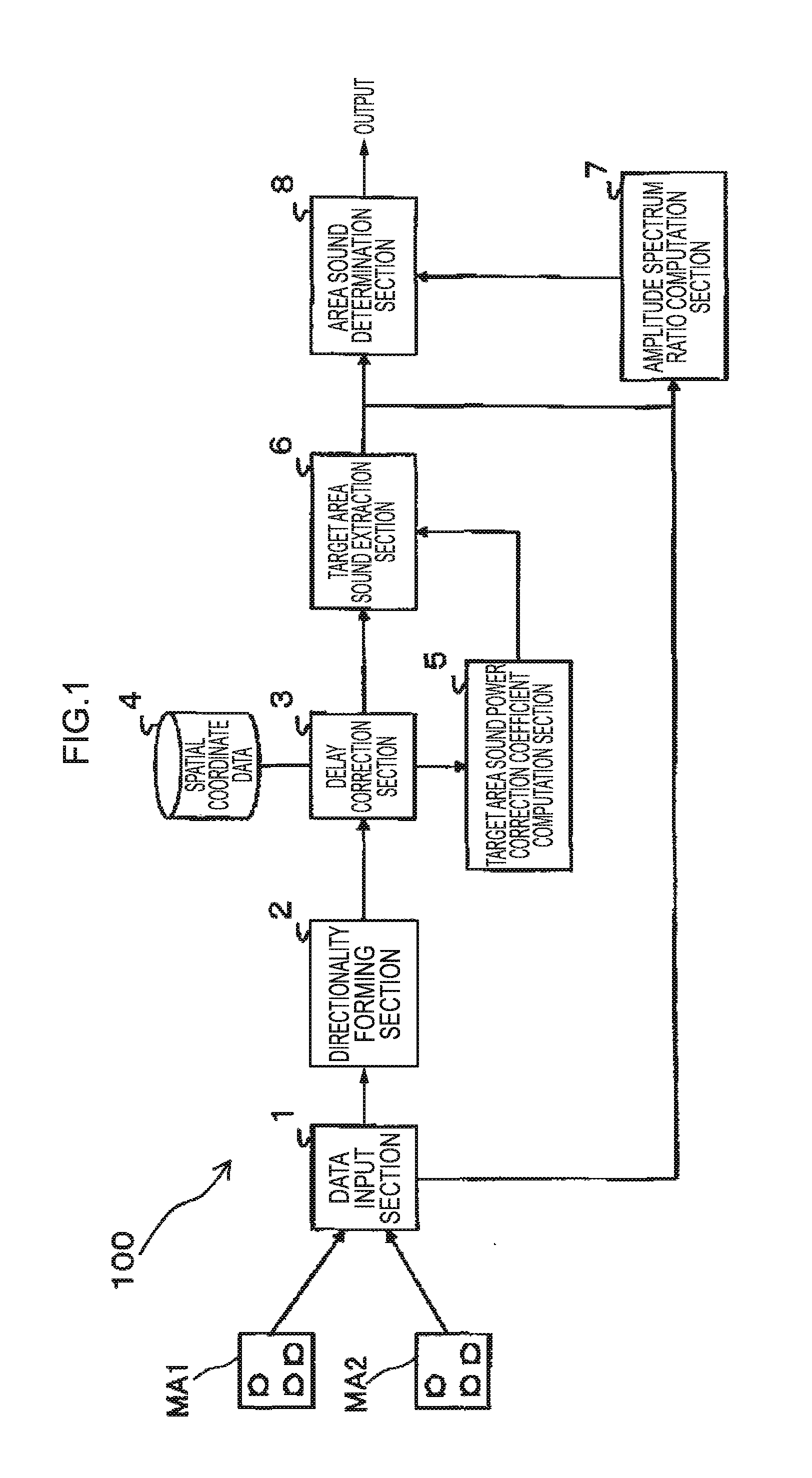
[0093]FIG. 7 is a block diagram illustrating a functional configuration of a sound pickup device 100A of a modified example of the first exemplary embodiment.
[0094]The sound pickup device 100A of the modified example of the first exemplary embodiment differs from the first exemplary embodiment in that a noise suppression section 9 is added. The noise suppression section 9 is inserted between the directionality forming section 2 and the delay correction section 3.
[0095]The noise suppression section 9 uses the determination result (a detection result indicating segments in which target area sound is present) of the area sound determination section 8 to perform suppression processing on noise (sounds other than target area sound) for the respective BF outputs Y1, Y2 output from the directional...
second exemplary embodiment
(C-2) Operation of Second Exemplary Embodiment
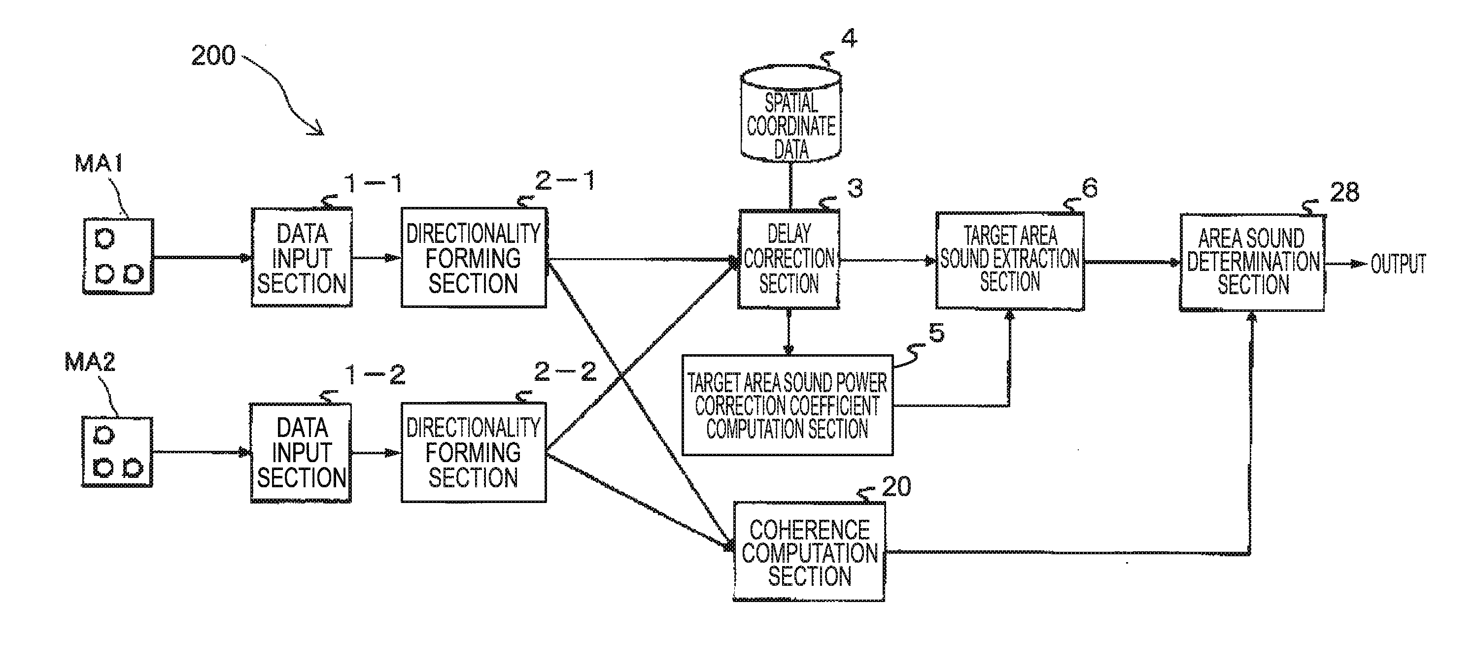
[0104]The data input sections 1-1, 1-2 perform processing to receive a supply of analog signals of audio signals captured by the microphone arrays MA1 and MA2 respectively, convert the analog signals into digital signals, and supply the digital signals to the directionality forming sections 2-1 and 2-2 respectively.
[0105]The directionality forming sections 2-1, 2-2 perform processing to form directionality for the microphone arrays MA1 and MA2 respectively (to form directionality in the signals supplied from the microphone arrays MA1 and MA2).
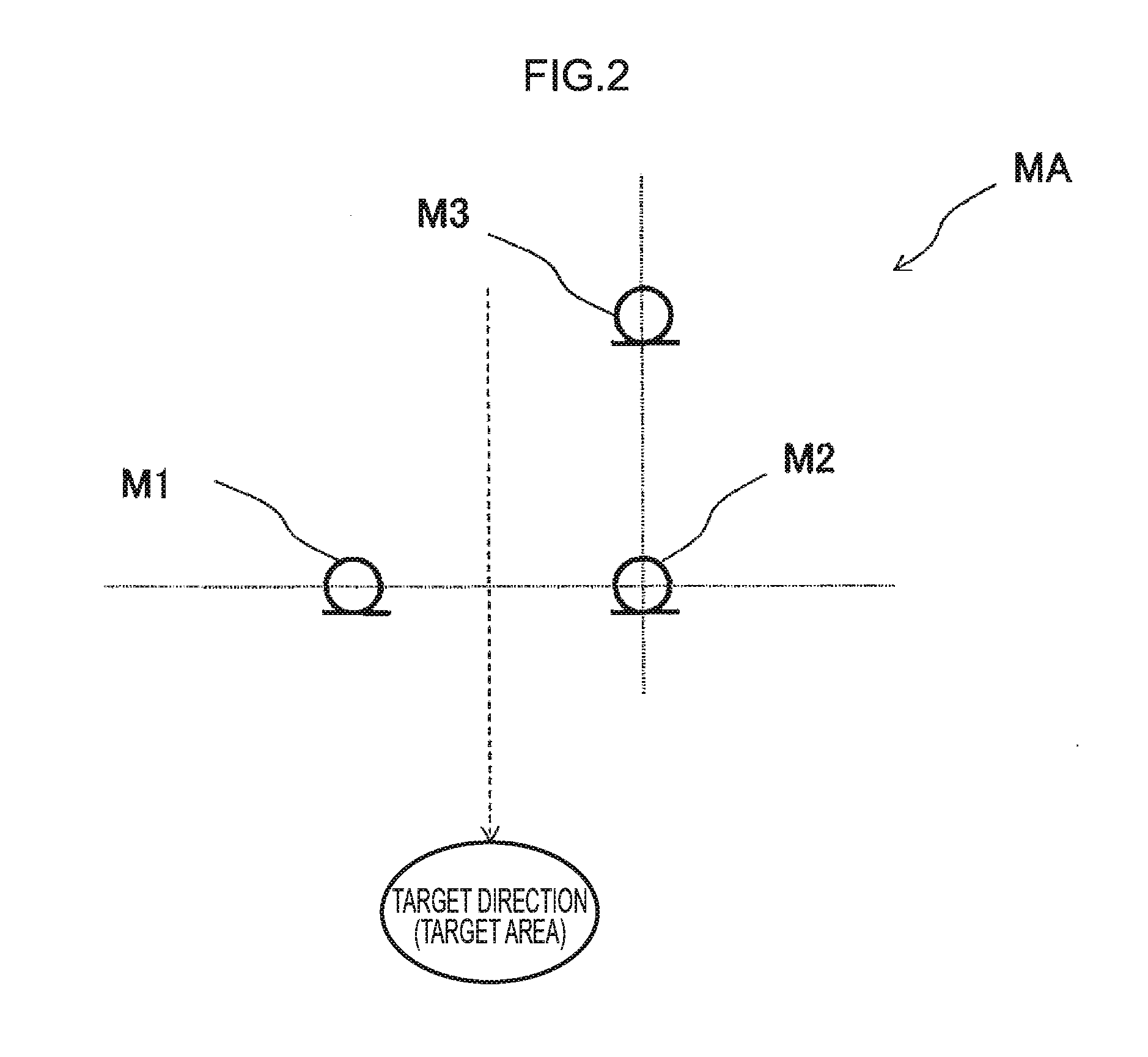
[0106]The directionality forming sections 2-1 and 2-2 each perform conversion from the time domain into the frequency domain using a fast Fourier transform. In the present exemplary embodiment, each of the directionality forming sections 2-1 and 2-2 forms a bidirectional filter using the microphones M1 and M2 that are arranged in a row on a line perpendicular to the direction of the target area, and...
third exemplary embodiment
(F) Modified Example of Third Exemplary Embodiment
[0156]FIG. 17 is a block diagram illustrating a functional configuration of a sound pickup device 300A of a modified example of the third exemplary embodiment.
[0157]The sound pickup device 300A of the modified example of the third exemplary embodiment differs from the third exemplary embodiment in that two noise suppression sections 10 (10-1, 10-2) are added. The noise suppression sections 10-1 and 10-2 are inserted, respectively, between the data input sections 1-1, 1-2 and the directionality forming sections 2-1, 2-2. Moreover, the outputs of the noise suppression sections 10-1, 10-2 are also supplied to the amplitude spectrum ratio computation section 37.
[0158]The noise suppression sections 10-1, 10-2 use the determination results of the area sound determination section 38 (the detection results for the segments in which target area sound is present) to perform suppression processing for noise (sounds other than target area sound)...
PUM
 Abstract
Description
Claims
Application Information
 - R&D
- Intellectual Property
- Life Sciences
- Materials
- Tech Scout
- Unparalleled Data Quality
- Higher Quality Content
- 60% Fewer Hallucinations
Browse by: Latest US Patents, China's latest patents, Technical Efficacy Thesaurus, Application Domain, Technology Topic, Popular Technical Reports.
© 2025 PatSnap. All rights reserved.Legal|Privacy policy|Modern Slavery Act Transparency Statement|Sitemap|About US| Contact US: help@patsnap.com


