Method of Reducing and Optimising Printed Support Structures in 3D Printing Processes

a printing process and printing technology, applied in the direction of additive manufacturing processes, manufacturing tools, manufacturing data acquisition/processing, etc., can solve the problems of reducing adding both considerable cost and time to the 3d printing of certain target model configurations, and requiring the formation of supporting materials, so as to reduce the volume of required model materials and increase the printing efficiency of 3d printers. , the effect of less tim

Active Publication Date: 2016-07-14
UNIVERSITY OF WINDSOR
View PDF10 Cites 36 Cited by
  • Summary
  • Abstract
  • Description
  • Claims
  • Application Information

AI Technical Summary

Benefits of technology

[0024]Preferably, the sides of the cap portion extend outwardly relative to the support web at locations spaced above the virtual printer table selected so that each side meets the underside of the identified portion requiring support at a widest possible point. Each cap portion may be infilled with the printer material to form a solid or partially open bearing surface for the model in the horizontal direction. In one possible construction, the V-shaped cap portion may be substantially infilled with a secondary low density printer formed support material. The low density material being selected to provide sufficient vertical support for the printed model, whilst reducing the volume of printer material required for support structure formation. Suitable low density infill material could for example include without restriction printed ABS or other plastic filaments.
[0026]In another possible construction, the trough or cap portion is supported by a primed web which is formed having one or more axially spaced pillars, splayed or fanned tops and / or diamond-shaped cut outs, holes and / or other apertures to reduce the volume required model material. Where apertures or diamond-shaped cut outs are provided, preferably each of the sides of the web defining the aperture or diamond extend an angle relative to vertical no greater than the overhang angle of the material being used.
[0027]Following computer modelling, the computer is used to actuate the 3D printer to simultaneously print the target model und support structures in accordance with the generated virtual models. In a preferred method, the sides of the cap portion are formed so as to follow a contour of the target model to provide full three dimensional support. Depending on the size of the target model, over a given area of one or more model portion requiring support, as few as one and possibly multiple discrete support structures may be used. The support structures could include in the alternative or in addition to troughs, pillar and / or wall or web structures which are individually designed for the model size and weight of the target model being supported. Preferably, the support structures are provided to optimize the material used against the structure complexity of the target model, to increase the printing efficiency of the 3D printer.
[0028]The system printer may thus be activated to effect formation of required printer-formed supports in substantially the same locations on a target model as conventional printing processes, whilst depending on target model, using upto less than a quarter or more of the support material compared with conventional printing processes. It is recognized that printing of such support materials may thus be achieved in less time, whilst resulting in substantial material and time saving to produce the same 3D target model. Such time savings further may be used to increase production capacity on 3D printing machines, reducing costs.
[0029]The invention may also provide for a method of forming 3D primed support structures required to build various target model configurations in 3D printing, whilst using less material, and which in turn, reduces overall printing time. In a most simplified mode, printing of the support structures is achieved using the same or very similar hardware as those used to print the model itself. Printing may thus be performed using available 3D printing systems and which include without restriction, systems which operate by placing or depositing material by thermal plastic extrusion; as well as systems that deposit material through a specialized (i.e. dot Matrix) printing heads that place polymers with a binder material that adheres / fuse to already deposited material. In such systems the manufacturers may determine, based at least in part on the properties of the material used to form the target model, where the target model will require support structures to be built successfully.

Problems solved by technology

This adds both considerable cost and time to the 3D printing of certain target model configurations.
Both the material and machine lime to place and form the support material is a necessary non-value added cost.

Method used


Image

  • Method of Reducing and Optimising Printed Support Structures in 3D Printing Processes
  • Method of Reducing and Optimising Printed Support Structures in 3D Printing Processes
  • Method of Reducing and Optimising Printed Support Structures in 3D Printing Processes

Examples


Embodiment Construction

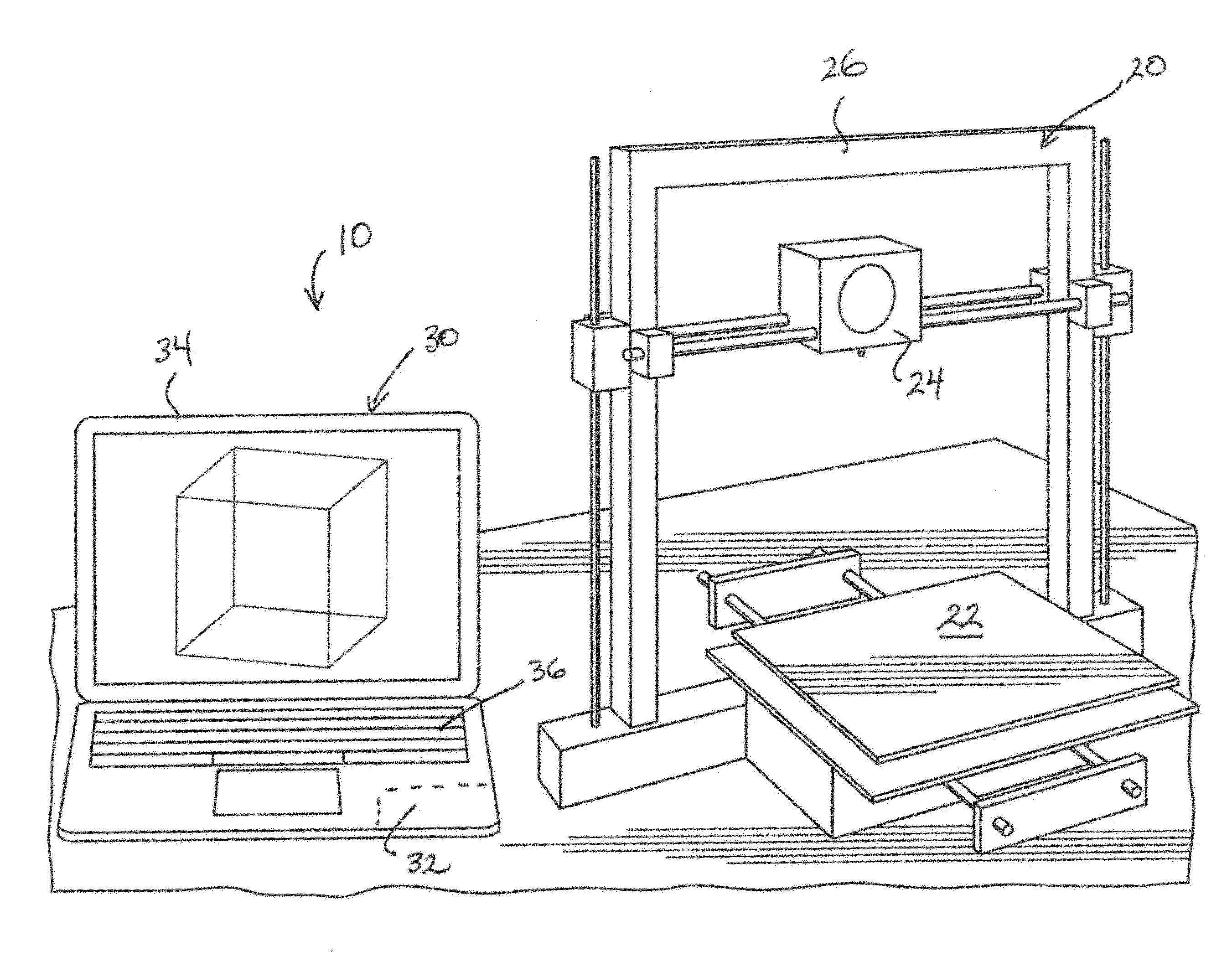
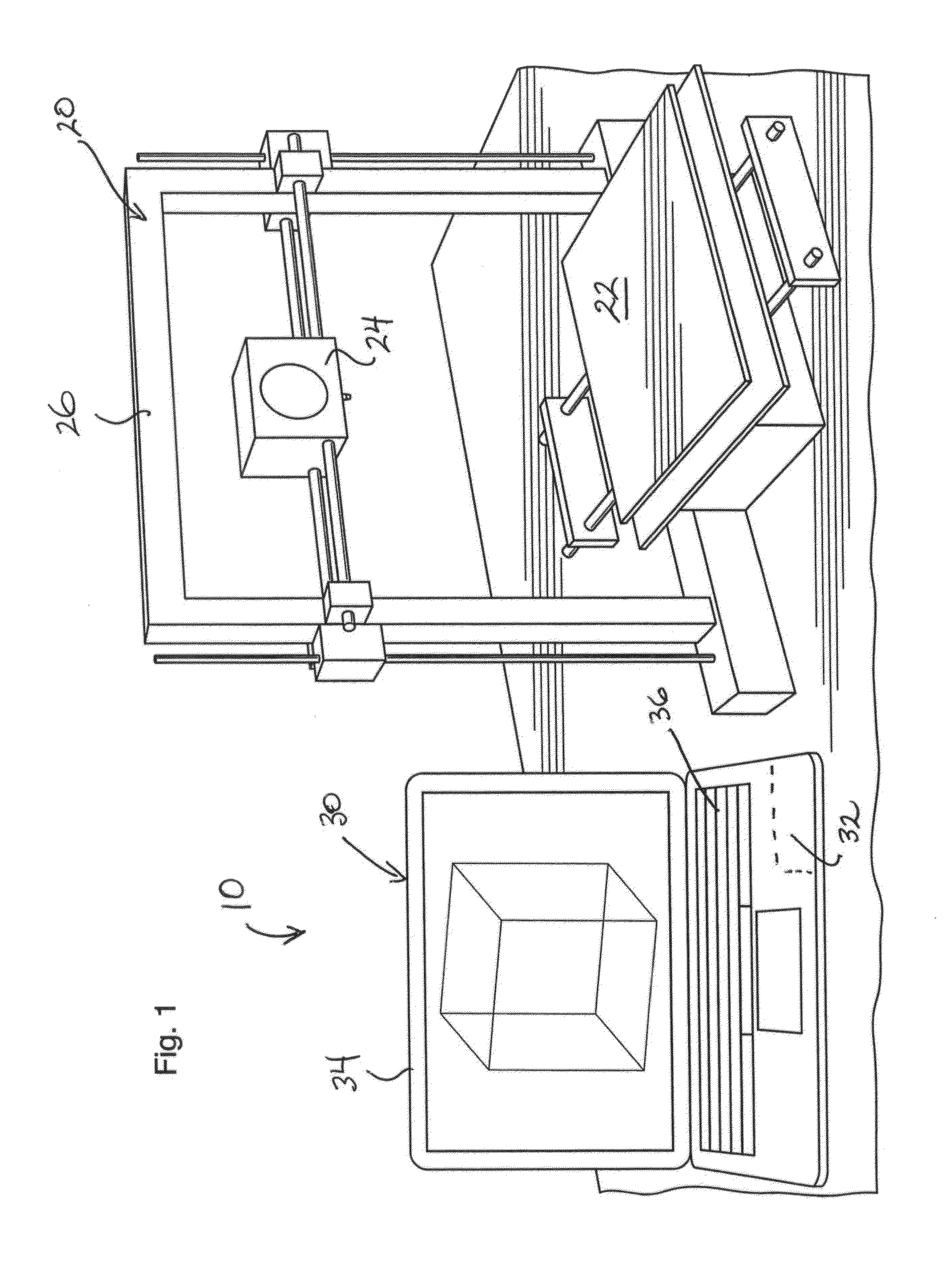
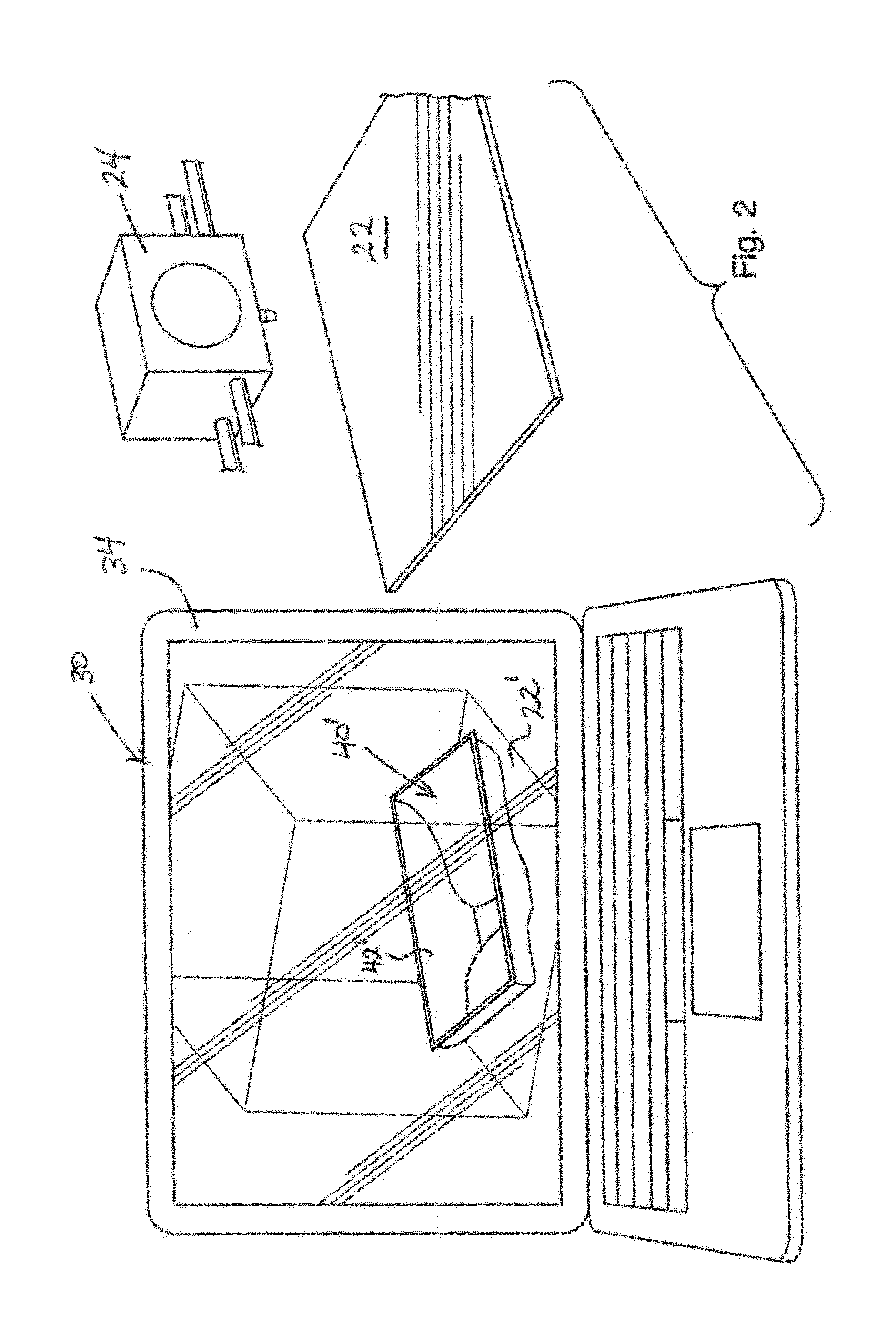
[0041]Reference may now be bad to FIG. 1 which illustrates a 3D printer assembly 10 in accordance with a preferred embodiment of the invention. The printer assembly 10 includes a 3D printer 20, having a printer table 22 and printer head 24 which is movable in three axis relative to the printer table 22 on a gantry frame 26. The 3D printer 20 is controlled a computer 30 which includes a proccessor 32 having memory, as well as a video display 34 and keyboard 36.

[0042]As will be described, the printer assembly 10 is operable for use in the automated design building of a selected target model 40 (shown in FIG. 11). In the detailed description, and by way of non-limiting example, the target model 40 is described and illustrated as raised platform 42. As will described, the raised platform 42 is structurally supported during formation by the printing process by way of one or more integrally formed 3D printed pillars or support structures 50.

[0043]Although not essential, most preferably th...


PUM

PropertyMeasurementUnit
threshold angleaaaaaaaaaa

Abstract

A printed target model is formed by 3D printing by inputting target model data, and based on target model data, identifying surface portions requiring support. The surface portions are projected onto a virtual printer table, and one or more virtual support structures having a V-shaped cap portion and optionally a generally planar web are created therefore. The virtual model is then used to control a 3D printer to integrally print-form the target model and support structures.

Description

RELATED APPLICATIONS[0001]This application claims priority to and the benefit of 35 USC §119(c) to U.S. Patent Application Ser. No. 62 / 102,627, filed Jan. 13, 2015, the entirety of which is incorporated herein by reference.SCOPE OF THE INVENTION[0002]The present invention relates to a method and apparatus for reducing and optimising the amount of printed support structure material used in printing target models or other articles or structures which are formed by three-dimensional (3D) printing processes.BACKGROUND OF THE INVENTION[0003]3D printing is able to build complex and functional three dimensional objects or target models front various metals, plastic polymers, paper, and modified clays. When printing three-dimensional articles or target models, the printed article will be subject to a threshold overhang angle of departure. The threshold overhang angle is the maximum angle relative from vertical at which the part of the model may be printed without collapsing or deforming dur...

Claims


Application Information

Patent Timeline
Patent Type & Authority Applications(United States)
IPC IPC(8): B29C67/00B28B1/00
CPCB29C67/0088B29C67/0055B29C67/0092B28B1/001B33Y50/02B29K2995/0037B29K2001/00B33Y10/00B29K2105/0058B29C64/40B29C64/393B29C64/106
Inventor URBANIC, JILL
Owner UNIVERSITY OF WINDSOR
Why Eureka
Try Eureka