Aircraft autonomous pushback

a technology of autonomous pushback and aircraft, which is applied in the direction of energy-saving operation measures, aircraft braking arrangements, wheel arrangements, etc., can solve the problems of not being able to use brake pedals, damaging nose landing gear and tractor, and not being able to operate civil aircra

Active Publication Date: 2016-07-14
AIRBUS OPERATIONS LTD
View PDF0 Cites 17 Cited by
  • Summary
  • Abstract
  • Description
  • Claims
  • Application Information

AI Technical Summary

Benefits of technology

[0006]A further aspect of the invention provides an autonomous pushback braking system for an aircraft having a wheel drive system for driving one or more of the aircraft's landing gear wheels in rotation, wherein the wheel drive system is operable to drive the wheel in rotation to effect backwards motion of the aircraft when in contact with the ground, and a means for applying a torque to at least one landing gear wheel of the aircraft, the torque being in a direction opposite to the backwards rolling direction of rotation of the landing gear wheel, and wherein the torque applied does not exceed a limit for ensuring aircraft longitudinal stability.
[0015]The braking control system may limit the maximum braking clamping pressure applicable to the friction brake assemblies to no more than a limit at which the aircraft longitudinal stability is ensured.

Problems solved by technology

Whilst some aircraft have the capability to reverse under their own power using the main aircraft engines, e.g. by using reverse thrust in a manoeuvre known as “power back”, this is not permitted for civil aircraft as the jet or prop wash from the engines can cause damage to nearby terminal buildings or facilities.
Use of the brake pedals is generally prohibited as there is a risk of damaging the nose landing gear and the tractor.
Conventional aircraft braking systems are typically not designed to perform this function, being more suited to high energy dissipation in the landing phase and low energy dissipation working against the thrust of the main aircraft engines in the taxi phase.
Conventional aircraft braking systems are therefore generally unsuited to braking during an autonomous pushback operation.
The autonomous pushback introduces the risk of aircraft tip over (where the aircraft tends to rotate nose up about its pitch axis, possibly causing a tail strike) and aircraft runaway (where if the autonomous pushback manoeuvre is performed on a slope the longitudinal component of the gravity acceleration can become higher than the rolling resistance of the tyres on the ground such that the aircraft accelerates above the desired pushback speed).

Method used


Image

  • Aircraft autonomous pushback
  • Aircraft autonomous pushback
  • Aircraft autonomous pushback

Examples


Embodiment Construction

)

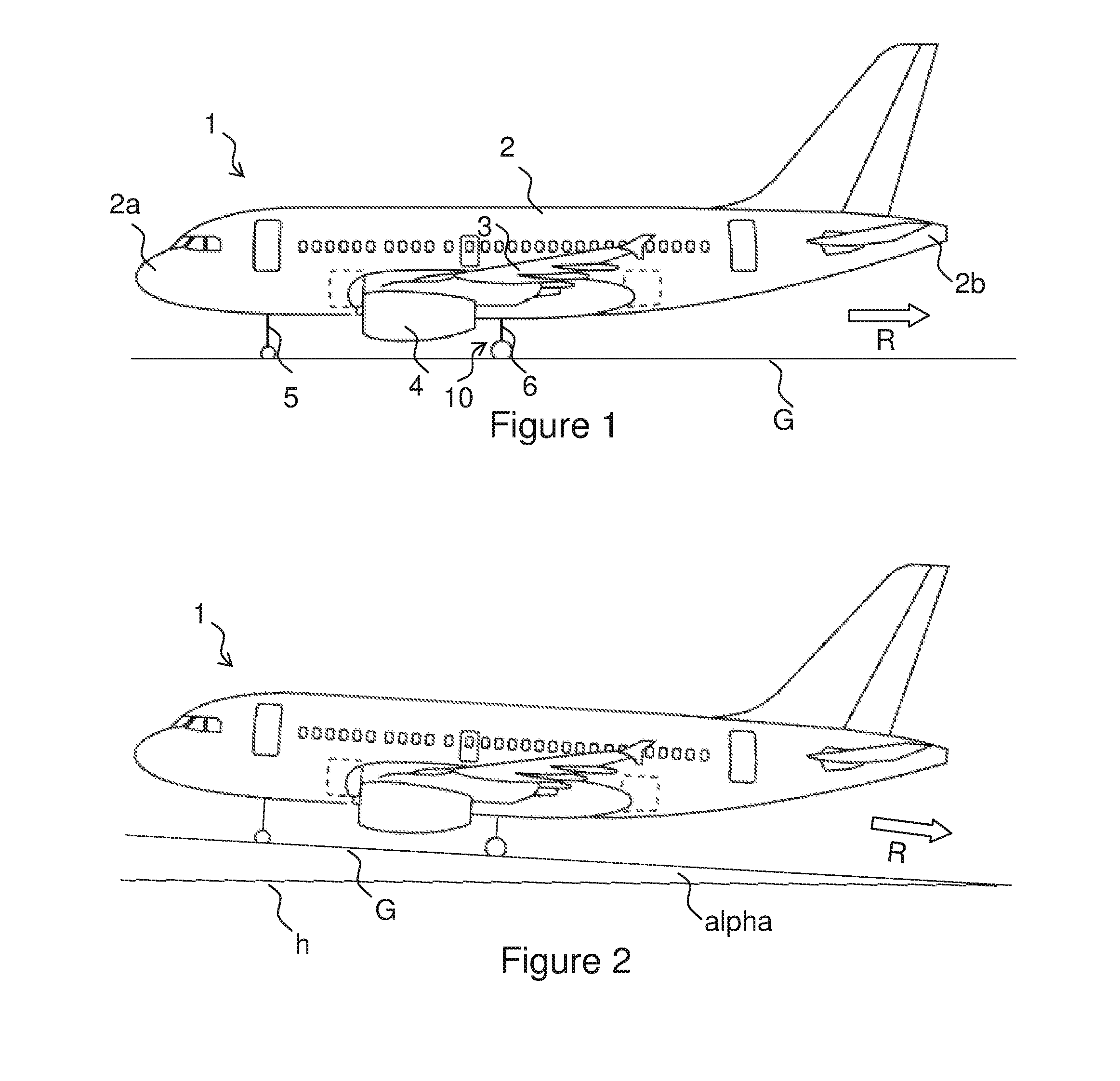
[0035]FIG. 1 shows an aircraft 1 having a fuselage 2 including a nose 2a and a tail 2b, wings 3, main engines 4, nose landing gear 5 and main landing gear 6. The aircraft has two main landing gears 6, one on either side of the aircraft centreline, and a single nose landing gear 5 forming a tripod. Each landing gear 5, 6 has a diablo configuration with two wheels.

[0036]The aircraft 1 is typical of a short range single aisle passenger jet aircraft, although it will be appreciated that the invention has applicability to a wide variety of aircraft types as mentioned above. In particular the aircraft may have a greater or fewer number of landing gears; and each landing gear may have any number of wheels, including one.

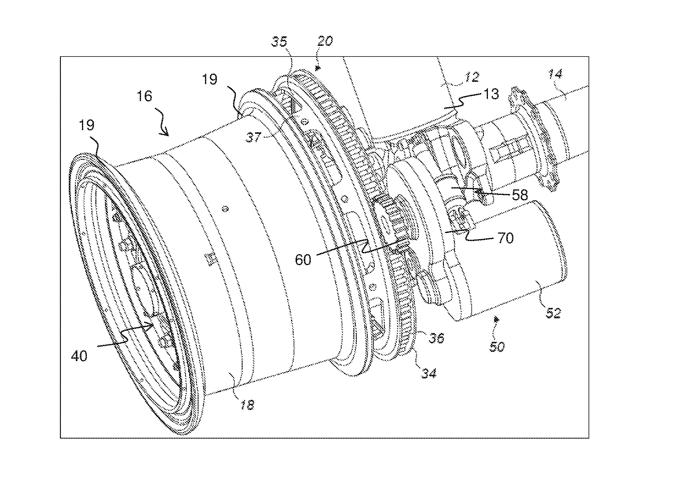
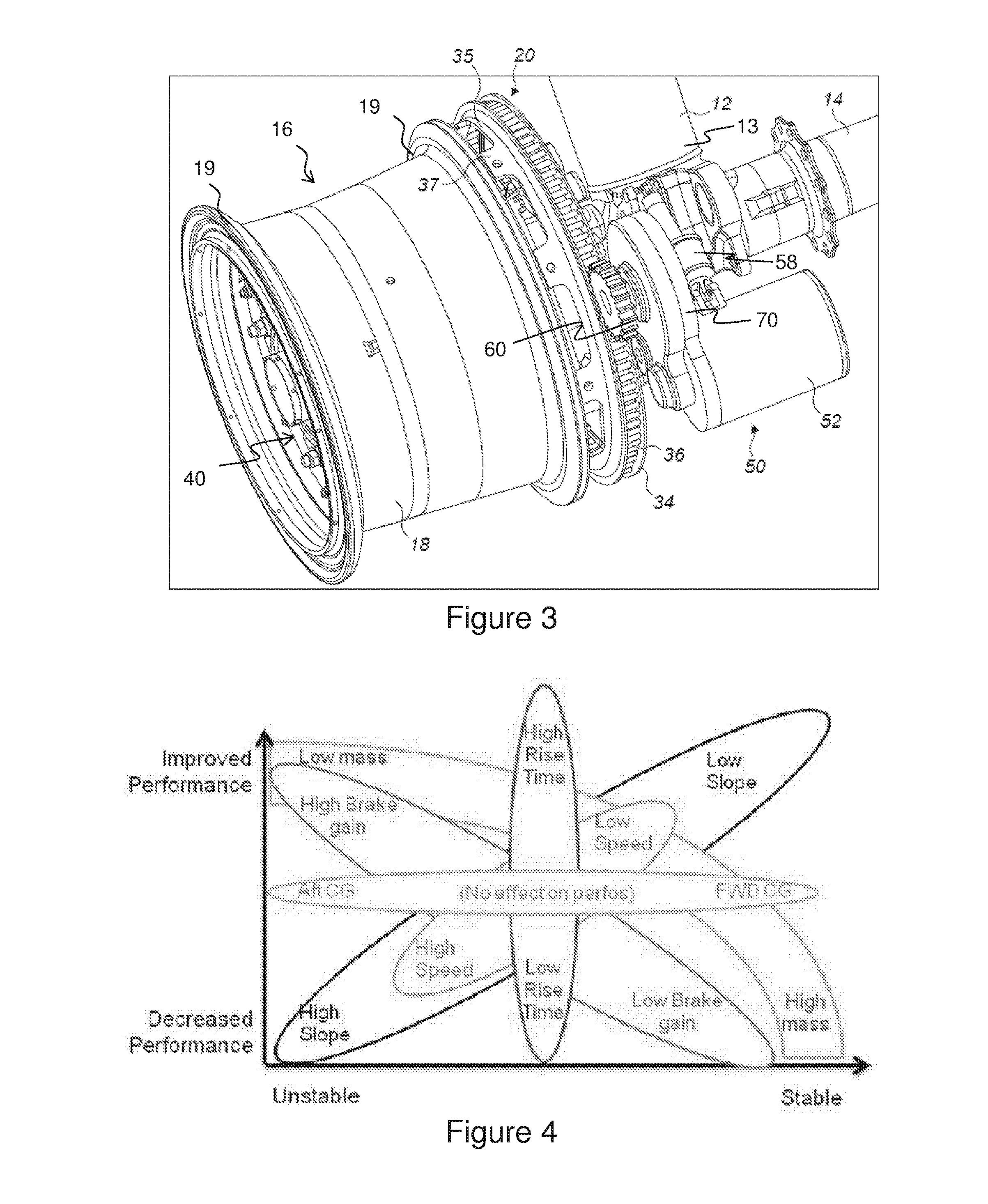
[0037]Each main landing gear 6 has a wheel drive system 10, shown in detail in FIG. 3. The wheel drive system 10 is for driving one wheel of the main landing gear 6 (typically the outboard wheel but may alternatively be the inboard wheel) in rotation to taxi the aircraft o...


PUM


Abstract

The invention provides methods and systems for controlling speed of an aircraft during an autonomous pushback manoeuvre, i.e. under the aircraft's own power without a pushback tractor. The method includes applying a torque to at least one landing gear wheel of the aircraft, the torque being in a direction opposite to the backwards rolling direction of rotation of the landing gear wheel. The torque applied does not exceed a limit for ensuring aircraft longitudinal stability. For longitudinal stability the torque applied should not cause the aircraft to risk a tip-over event.

Description

FIELD OF THE INVENTION[0001]The present invention relates to reversing of an aircraft on the ground using an autonomous taxiing system, and in particular the invention relates to decelerating the aircraft when reversing.BACKGROUND OF THE INVENTION[0002]It is sometimes necessary to move an aircraft in reverse whilst the aircraft is on the ground. For example aircraft are frequently pushed backwards away from an airport gate, a so called “pushback” manoeuvre, by a vehicle known as a pushback tractor or tug. The same tractor or tug can also move the aircraft forward if desired. Whilst some aircraft have the capability to reverse under their own power using the main aircraft engines, e.g. by using reverse thrust in a manoeuvre known as “power back”, this is not permitted for civil aircraft as the jet or prop wash from the engines can cause damage to nearby terminal buildings or facilities.[0003]Recently it has been proposed to equip aircraft with an autonomous wheel drive taxi system th...

Claims


Application Information

Patent Timeline
Patent Type & Authority Applications(United States)
IPC IPC(8): B64C25/44B64C25/40B64C25/34
CPCB64C25/445B64C25/405B64C25/34B60T8/00B60T8/1703Y02T50/80B60T8/32
Inventor MORRIS, JAMESCOLOSIMO, ANTONIO
Owner AIRBUS OPERATIONS LTD
Why Eureka
Try Eureka