
Payload Orientation Control and Stabilization

a technology for controlling and stabilizing the angular momentum and rotational movement of the payload, which is applied in the direction of process control, machine control, instruments, etc., can solve the problems of high degree of payload control and stability, high risk of external forces, and large destabilizing vibration and oscillation of the payload and the components

Active Publication Date: 2016-07-14
HOHEISEL RAYMOND +1
View PDF5 Cites 12 Cited by
  • Summary
  • Abstract
  • Description
  • Claims
  • Application Information

AI Technical Summary

Benefits of technology

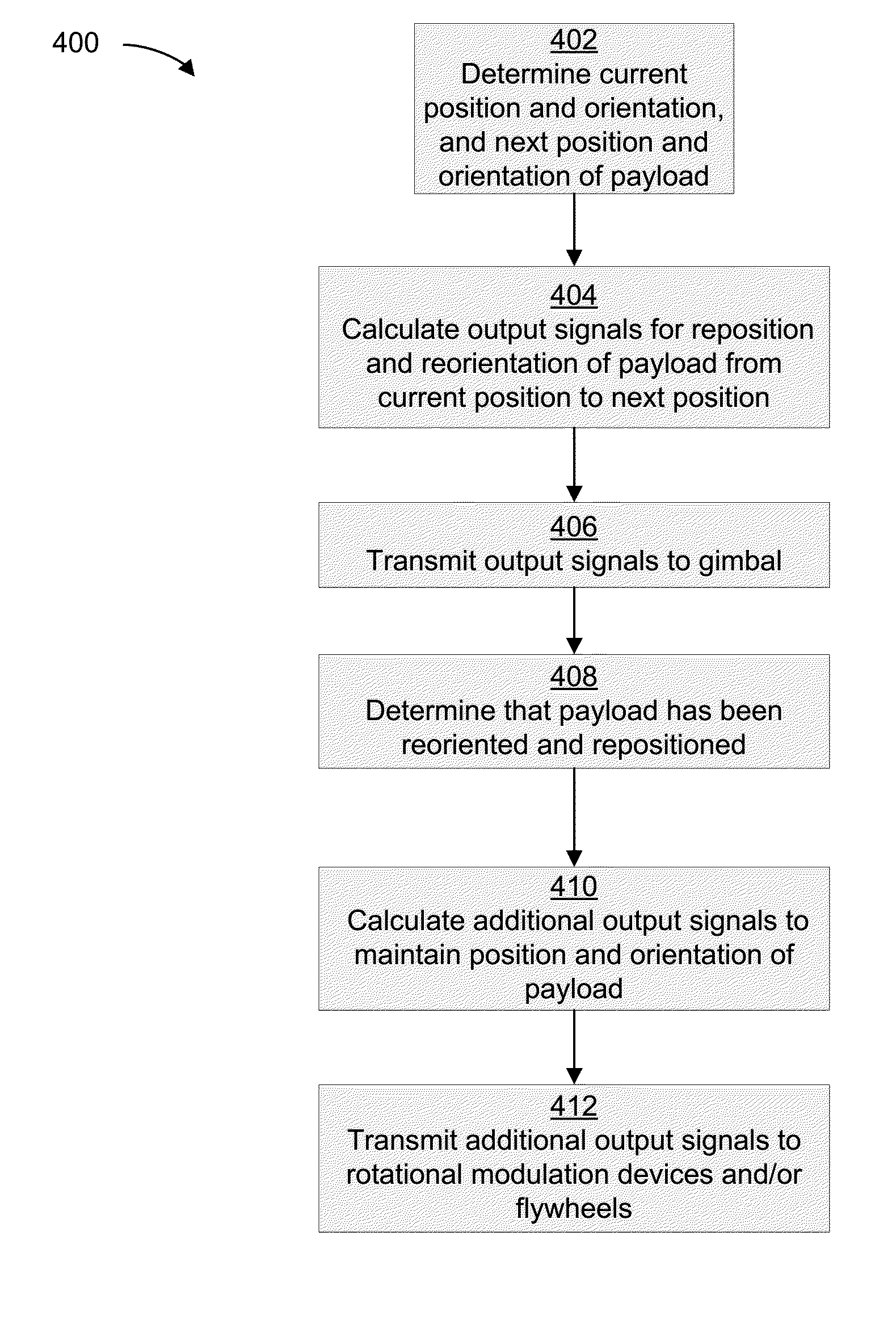
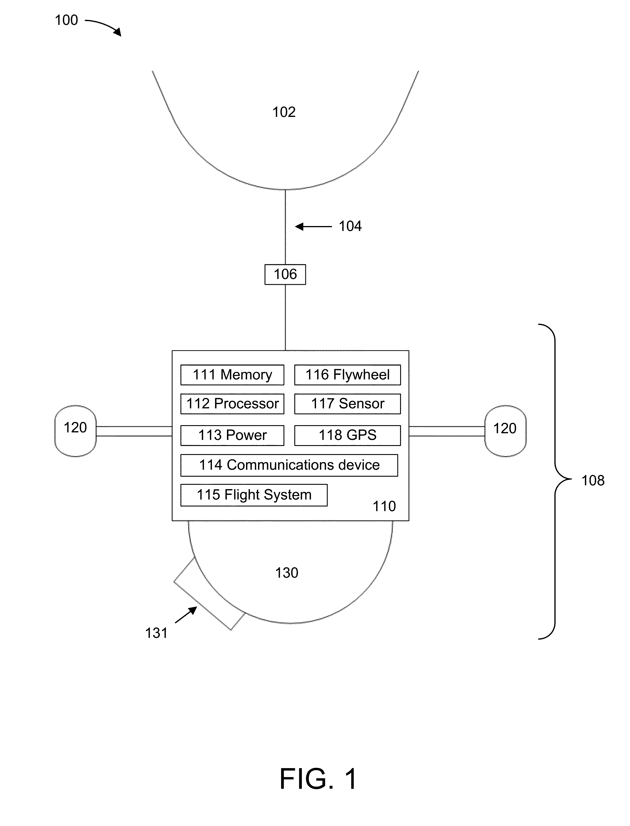
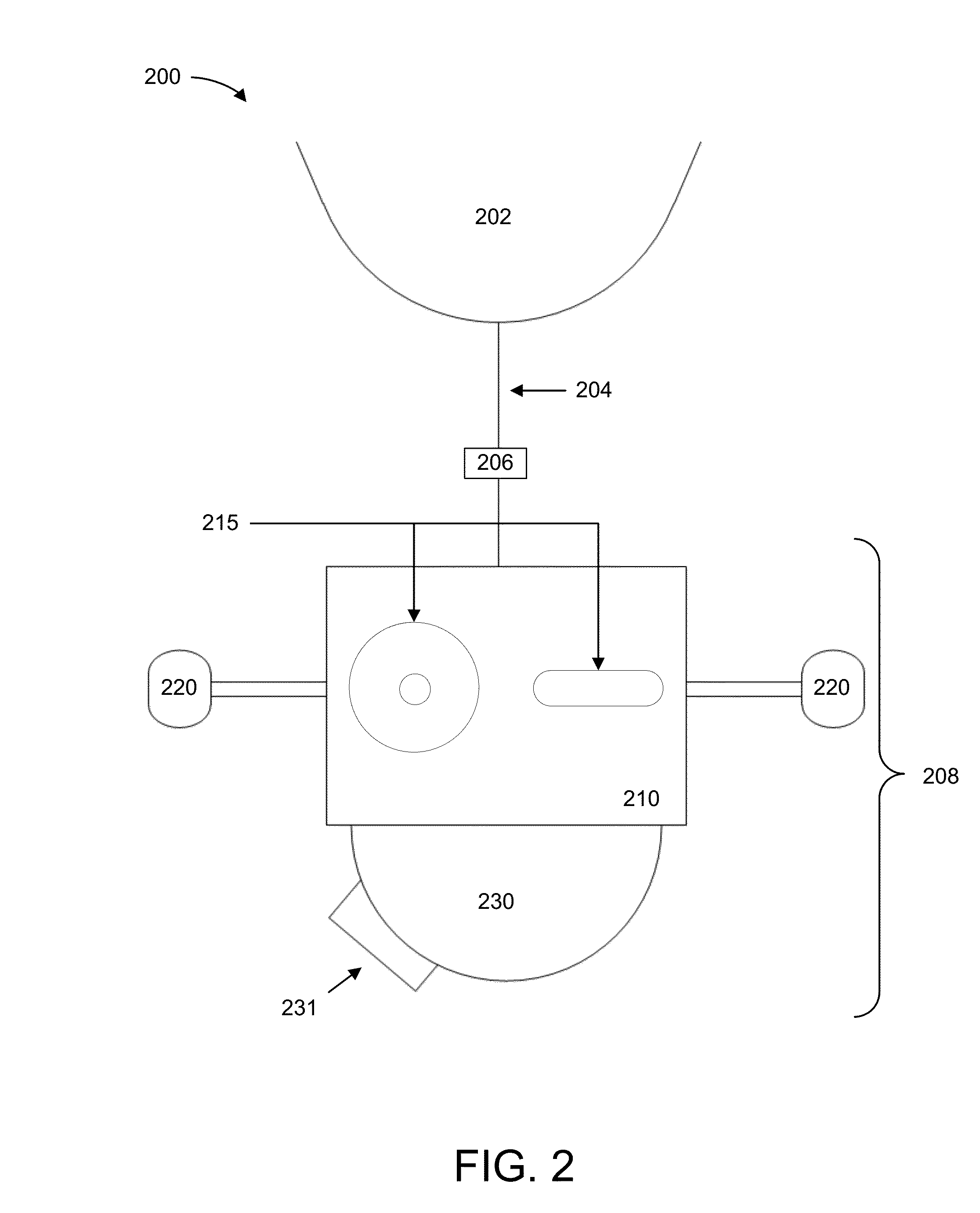
The patent describes apparatuses, systems, and methods for maintaining and stabilizing the position and orientation of a payload attached to a high-altitude balloon. This is achieved through the use of rotational stabilization devices, a powered gimbal, and a carousel device. The technology allows for the determination of the orientation and position of the payload, and the subsequent reorient and repositioning of the payload, carousel device, and hardware components in a new direction and orientation. The rotational stabilization devices act to rotate and stabilize the payload in the new direction. The technical effect of the technology is an improved ability to accurately position and orient payloads attached to high-altitude balloons.

Problems solved by technology

While the financial appeal for using high-altitude balloons for payload deployment is readily apparent, a number of technological issues currently inhibit the implementation in applications requiring a high degree of payload control and stability.
For example, balloon-mounted payloads are highly susceptible to externally applied forces from the immediate atmospheric conditions (e.g., wind, temperature, precipitation, and the like) as well as internal rotational forces generated by moving mechanical components operating within the attached payload.
Such effects, whether viewed alone or in combination, may generate significant destabilizing vibrations and oscillations of the payload and the components housed therein.
Consequently, balloon-mounted payloads fail to exhibit adequate directional control and / or stability required for many far reaching applications.

Method used


Image

  • Payload Orientation Control and Stabilization
  • Payload Orientation Control and Stabilization
  • Payload Orientation Control and Stabilization

Examples


Embodiment Construction

[0021]In the following description of the various embodiments, reference is made to the accompanying drawings, which form a part hereof, and in which is shown by way of illustration various embodiments in which aspects described herein may be practiced. It is to be understood that other embodiments may be utilized and structural and functional modifications may be made without departing from the scope of the described aspects and embodiments. Aspects described herein are capable of other embodiments and of being practiced or being carried out in various ways. Also, it is to be understood that the phraseology and terminology used herein are for the purpose of description and should not be regarded as limiting. Rather, the phrases and terms used herein are to be given their broadest interpretation and meaning. The use of “including” and “comprising” and variations thereof is meant to encompass the items listed thereafter and equivalents thereof as well as additional items and equivale...


PUM


Abstract

Systems and methods for maintaining and stabilizing the position and orientation of a payload attached to a high-altitude balloon are provided. A payload may be attached to a powered gimbal. The powered gimbal may be configured to orient and position the payload in a plurality of directions corresponding to a first, second, and third rotational axis of the balloon-mounted payload system. After the payload is positioned by the powered gimbal, the position and orientation of the payload may be maintained and stabilized by one or more rotational stabilization devices. The stabilization by the one or more rotational stabilization devices can occur along any one, or combination of, the first, second, and third rotational axes.

Description

[0001]This application claims priority to provisional U.S. Application Ser. No. 62 / 103,313, filed Jan. 14, 2015, entitled “Balloon Payload Orientation Control and Stabilization,” herein incorporated by reference for all purposes.FIELD[0002]Aspects described herein are generally related to controlling and stabilizing the angular momentum and rotational movement of payloads attached to a high-altitude balloon. More specifically, aspects of the disclosure relate to apparatuses, systems, and methods for maintaining and stabilizing the position and orientation of a payload attached to a high-altitude balloon.BACKGROUND[0003]High-altitude balloons have emerged as an increasingly utilized tool for the deployment of research, surveillance, and reconnaissance payloads. As compared to conventional means for payload deployment such as rockets and aircraft which are technologically complex and capital-intensive, high-altitude balloons present a mechanically simple and low-cost alternative.[0004...

Claims


Application Information

Patent Timeline
IPC IPC(8): G05D1/08B64D1/02B64B1/40
CPCG05D1/0816B64D1/02B64B1/40G05D1/0094B64B1/22B64B1/38B64B1/48H04N23/50H04N23/60H04N5/00
Inventor HOHEISEL, RAYMONDLORENTZEN, JUSTIN
Owner HOHEISEL RAYMOND
Learn More