Lte-a systems and method of drs based positioning

a positioning system and positioning technology, applied in the field of radio access networks, can solve the problems of ineffective positioning determination based on gps signals, increased communication traffic, and inability to provide gps in certain areas

Active Publication Date: 2016-07-14
APPLE INC
View PDF4 Cites 53 Cited by
  • Summary
  • Abstract
  • Description
  • Claims
  • Application Information

AI Technical Summary

Benefits of technology

[0064]Such embodiments of the inventive subject matter may be referred to herein, individually and/or collectively, by the term “invention” merely for convenience and without intending to voluntarily limit the scope of this application to any single invention or inventive concept if more than one is in fact disclosed. Thus, although specific embodiments have been illustrated and described herein, it should

Problems solved by technology

While position determination for E911 services is mandated by the Federal Communications Commission (FCC), in a number of cases, position determination based on GPS signals is ineffective.
In particular, GPS may not be available in certain areas due to blockage of the satellite signals, such inside buildings or other areas where the UE may be unable to detect signals from a sufficient number of GPS satellites.
Unfortunately, the most recent release (release 12) of the 3rd Generation Partnership Project (3GPP) standard for Long-Term-Evolution (LTE) networks contains updated requirements that serve to undermine position determination.
As the demand for communicating data (e.g., voice and video) has continued to increase, a RAN may experience increasingly heavy communication traffic.
This can lead to adverse network effects such as reduced data rates.
However, because the WLAN network operates in an unlicensed band, availability and characteristics of the channels operating in the band may cause difficulties in providing positional information.
While GPS/GNSS is a common method of obtaining the location of a UE, as discussed above however, in situation

Method used


Image

  • Lte-a systems and method of drs based positioning
  • Lte-a systems and method of drs based positioning
  • Lte-a systems and method of drs based positioning

Examples


Embodiment Construction

[0011]The following description and the drawings sufficiently illustrate specific embodiments to enable those skilled in the art to practice them. Other embodiments may incorporate structural, logical, electrical, process, and other changes. Portions and features of some embodiments may be included in, or substituted for, those of other embodiments. Embodiments set forth in the claims encompass all available equivalents of those claims.

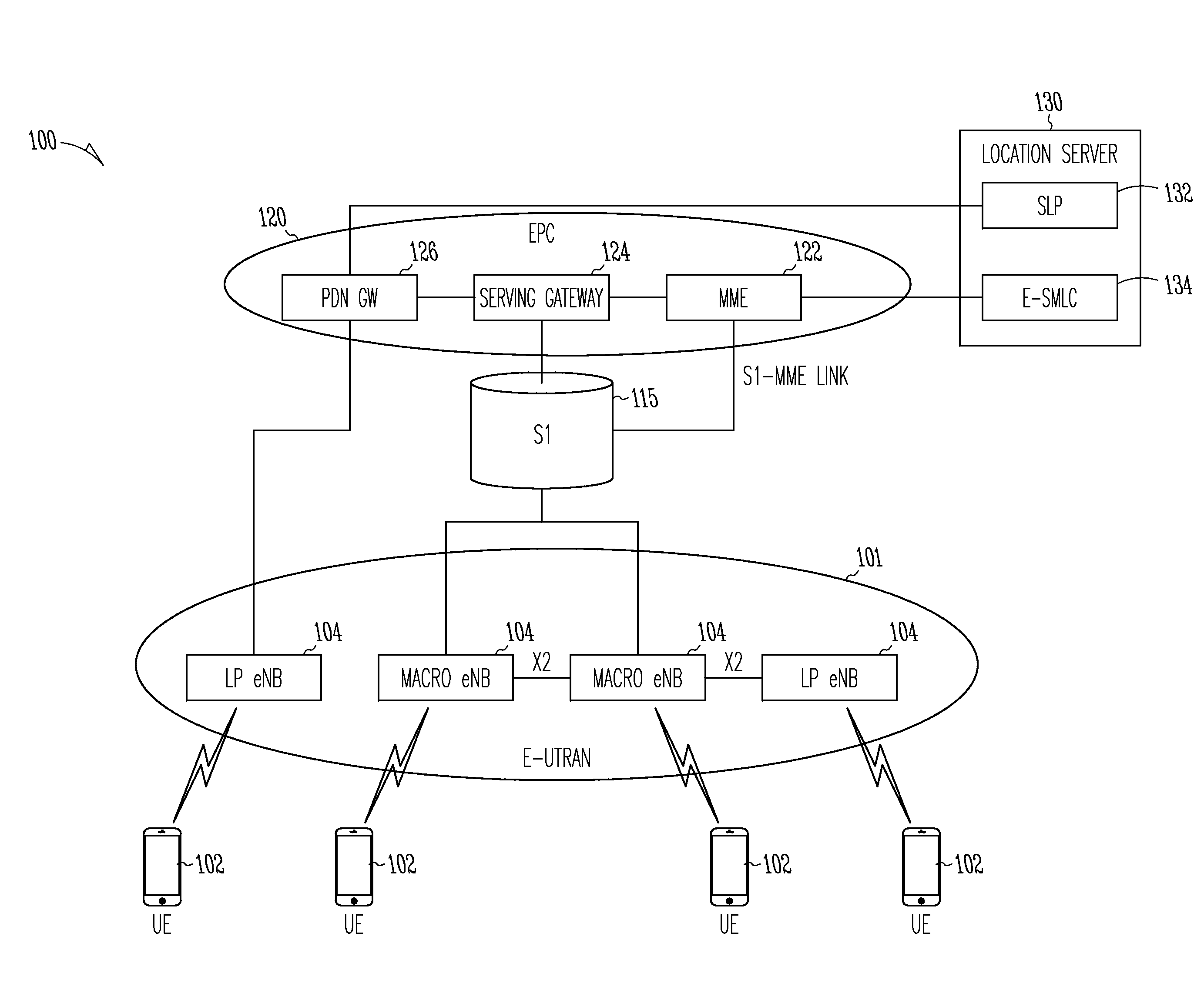
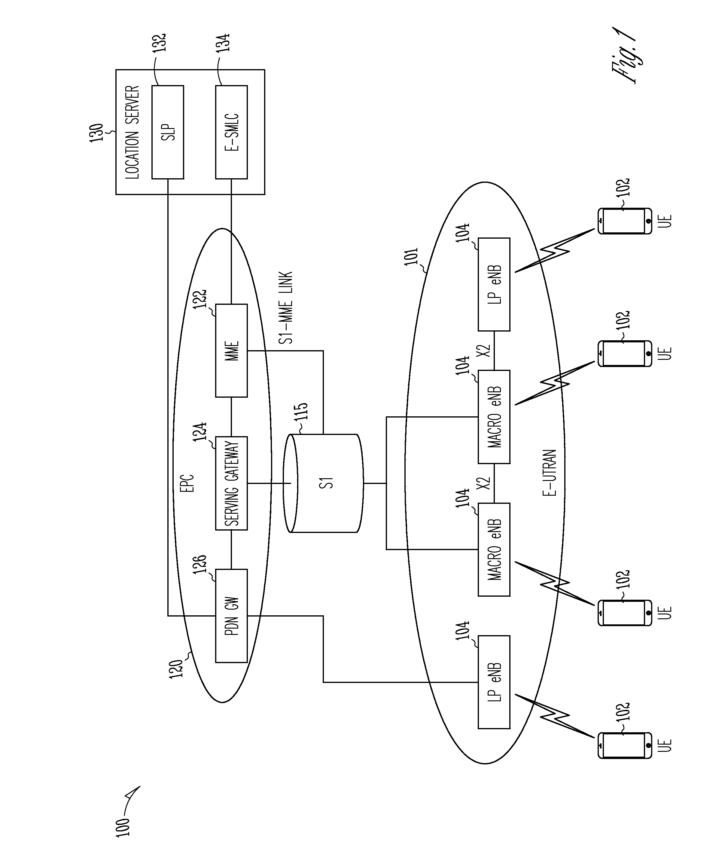
[0012]FIG. 1 shows an example of a portion of an end-to-end network architecture of a Long Term Evolution (LTE) network with various components of the network in accordance with some embodiments. As used herein, an LTE network refers to both LTE and LTE Advanced (LTE-A) networks. The network 100 may comprise a radio access network (RAN) (e.g., as depicted, the E-UTRAN or evolved universal terrestrial radio access network) 101 and the core network 120 (e.g., shown as an evolved packet core (EPC)) coupled together through an S1 interface 115. For conven...


PUM


Abstract

A Long Term Evolution Advanced (LTE-A) location server, user equipment (UE) and evolved Node-B (eNB) are generally described. Information may be transmitted to the UE from the location server. The transmission may be triggered by the location server or another entity requesting the UE location. The information may permit the UE to receive a discovery reference signal (DRS) from at least one eNB. The information may contain an indication of measurements to be performed using the DRS. The UE may measure Reference Signal Received Power (RSRP) or Reference Signal Time Difference (RSTD) of the DRS. The UE may send the measurement information to the location server where the UE location is estimated. The UE location may be based on measurements of the DRS and a positioning reference signal (PRS) from one or more eNBs to obtain the Observed Time Difference of Arrival (OTDOA) or Enhanced Cell ID (ECID).

Description

PRIORITY CLAIM[0001]This application claims the benefit of priority to U.S. Provisional Patent Application Ser. No. 62 / 102,180, filed, Jan. 12, 2015, and entitled “DISCOVERY REFERENCE SIGNALS BASED POSITIONING FOR LTE BASED SYSTEMS,” which is incorporated herein by reference in its entirety.TECHNICAL FIELD[0002]Embodiments pertain to radio access networks. Some embodiments relate to positional determination in cellular networks, such as Long Term Evolution (LTE) networks and LTE advanced (LTE-A) networks.BACKGROUND[0003]Today, mobile communications are ubiquitous, providing voice and data services via user equipment (UE) that operate on Long Term Evolution (LTE) networks such as mobile handset or smartphone type devices, tablets and laptop computers. Many services using mobile communications involve accurate device position determination of UEs, generally through the use of a Global Positioning System (GPS) or Global Navigation Satellite System (GNSS). For example, the commercial us...

Claims


Application Information

Patent Timeline
IPC IPC(8): H04W4/02H04W8/02H04W24/10
CPCH04W4/02H04W8/02H04W24/10G01S19/05G01S1/20G01S5/0036G01S5/0268G01S5/10G01S5/0236H04W64/00H04W64/003
Inventor DAVYDOV, ALEXEIFWU, JONG-KAE
Owner APPLE INC
Why Eureka
Try Eureka