Peeling bar for peeling polarizing film from panel, peeling apparatus and peeling method using the same

Active Publication Date: 2016-07-21
SHANJIN OPTOELECTRONICS SUZHOU CO LTD
View PDF26 Cites 7 Cited by
  • Summary
  • Abstract
  • Description
  • Claims
  • Application Information

AI Technical Summary

Benefits of technology

[0024]According to the present invention, since the polarizing film being peeled is in contact with the front part of the peeling bar, a frictional force applied to the polarizing film can be minimized and thus the fracture of the polarizing film can be prevented. Additionally, the radius of the curved surface at the tip of the front part and the inclined upper surface of the front part are designed to minimize the Z-axis component of a shearing force applied to the polarizing film, so that the fracture of the polarizing fi

Problems solved by technology

However, when the polarizing film is peeled from the panel, certain irregular tension applied to the polarizing film may cause the fracture of the polarizing film.
This fracture needs additional manual labor which is qu

Method used


Image

  • Peeling bar for peeling polarizing film from panel, peeling apparatus and peeling method using the same
  • Peeling bar for peeling polarizing film from panel, peeling apparatus and peeling method using the same
  • Peeling bar for peeling polarizing film from panel, peeling apparatus and peeling method using the same

Examples


Embodiment Construction

[0047]Hereinafter, the present invention will be described with reference to the accompanying drawings. However, well known or widely used techniques, elements, structures, and processes may not be described or illustrated in detail to avoid obscuring the essence of the present invention.

[0048]The terms and words used in the following description and claims are not limited to the bibliographical meanings, but are merely used by the inventor to enable a clear and consistent understanding of the present invention. Accordingly, it should be apparent to those skilled in the art that the following description of various embodiments of the present invention is provided for illustration purpose only and not for the purpose of limiting the present invention as defined by the appended claims and their equivalents.

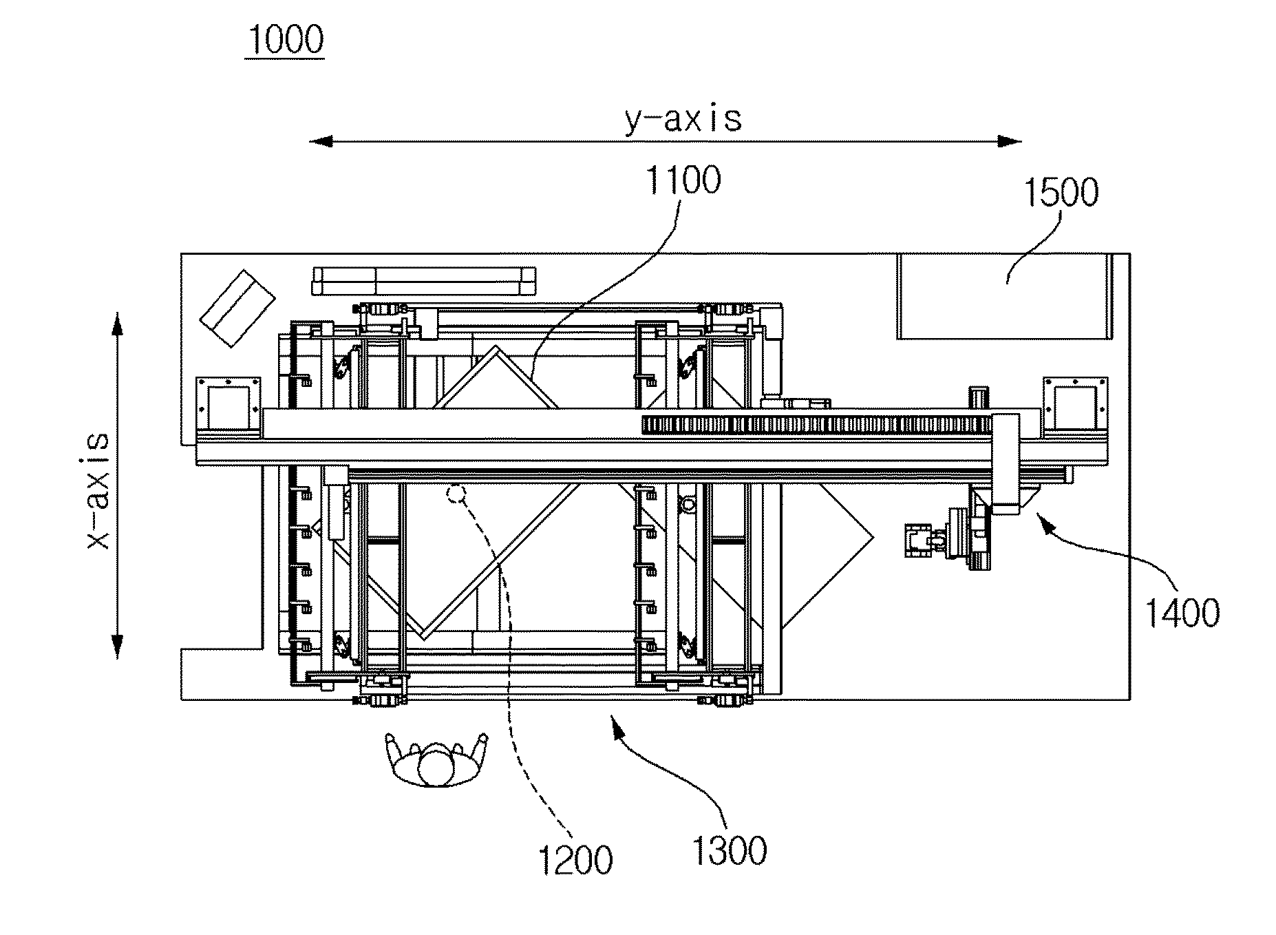
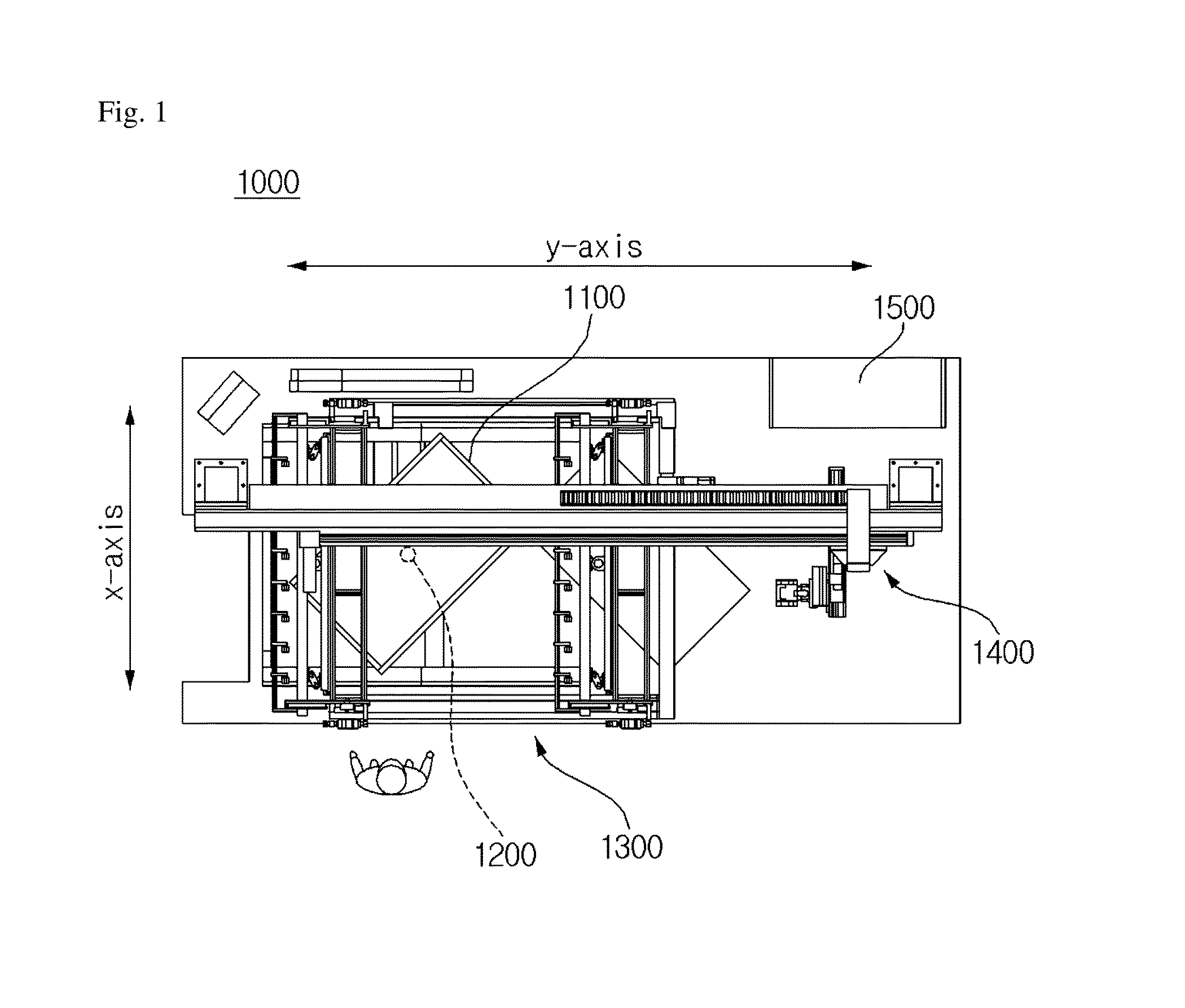
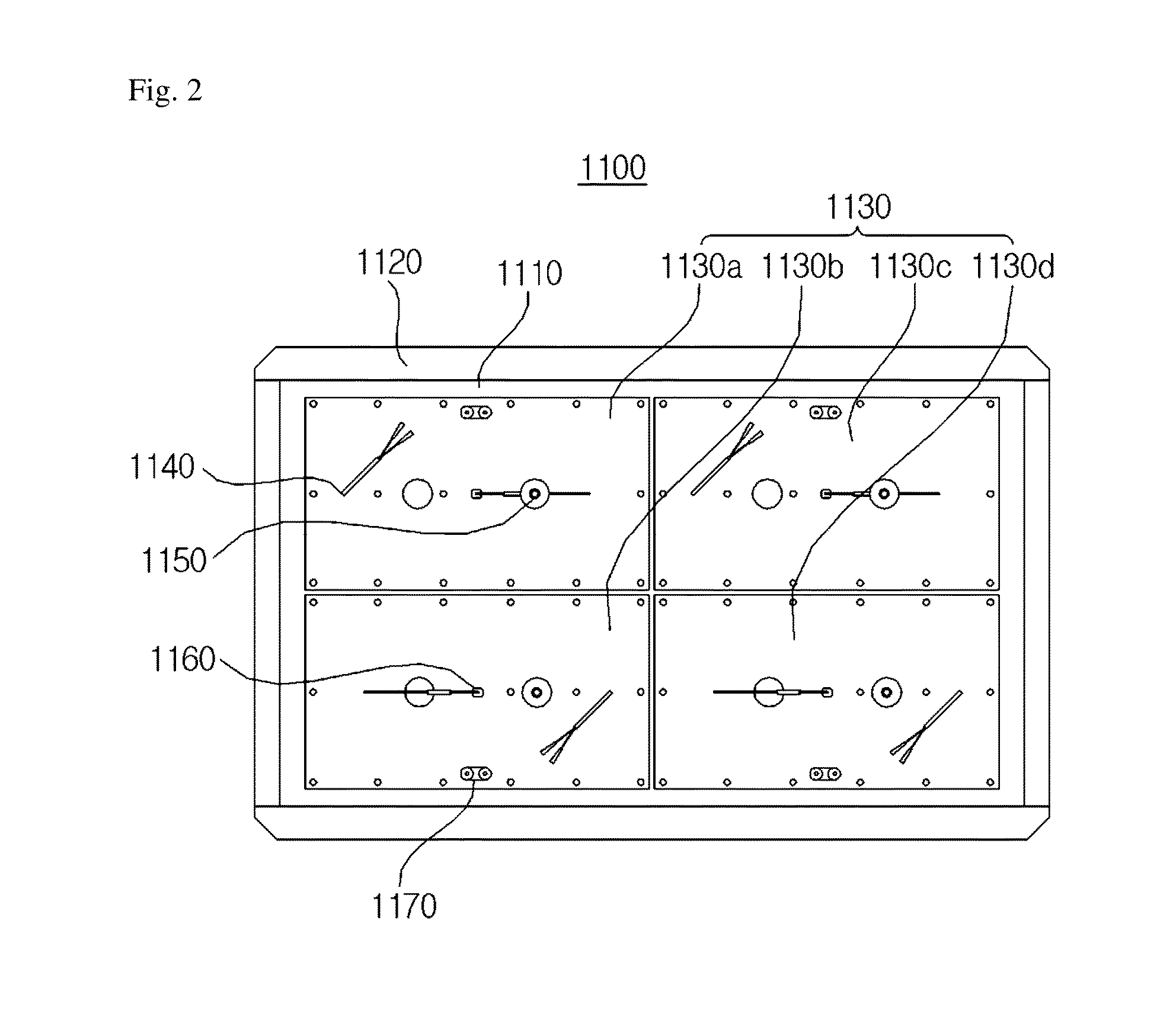
[0049]FIG. 1 is a plan view of an apparatus for peeling a polarizing film from a panel in accordance with an embodiment of the present invention, FIG. 2 is a plan view illustrating ...


PUM

PropertyMeasurementUnit
Angleaaaaaaaaaa
Angleaaaaaaaaaa
Radiusaaaaaaaaaa

Abstract

The present invention relates to a peeling bar, apparatus, and method for peeling a polarizing film from a panel. This invention can minimize friction between the peeling bar and the polarizing film since the peeled polarizing film is in contact with a front part of the peeling bar. The radius of a curved surface at the tip of the front part and an inclined upper surface of the front part are designed to minimize the Z-axis component of a shearing force applied to the polarizing film. Also, in order to equalize tension applied to the polarizing film in a peeling process, this invention makes both ends of the polarizing film closely adhere to the peeling bar. According to this invention, fracture of the polarizing film is prevented, and thereby the polarizing film can be stably peeled from the panel without fracture.

Description

TECHNICAL FIELD[0001]The present invention relates to technology of peeling a polarizing film from a panel and, more particularly, to a peeling bar, a peeling apparatus, and a peeling method for preventing the fracture of the polarizing film when peeling the polarizing film attached to the panel.BACKGROUND ART[0002]Normally a polarizing film is attached to a panel of an image display device and produces polarized light that vibrates in a specific direction and displays an image. Sometimes there may be bubble or any other foreign matter between the panel and the polarizing film. In this case, the polarizing film should be peeled from the panel by using a peeling apparatus.[0003]However, when the polarizing film is peeled from the panel, certain irregular tension applied to the polarizing film may cause the fracture of the polarizing film. This fracture needs additional manual labor which is quite cumbersome and also increases the entire time of a peeling process. Additionally, when s...

Claims


Application Information

Patent Timeline
IPC IPC(8): B65H41/00B32B43/00
CPCB65H41/00B65H2801/61B65H2301/51122B32B43/006B32B37/003B32B2307/42B32B2457/20B65H29/54Y10S156/93Y10S156/941Y10T156/1168Y10T156/1174Y10T156/195Y10T156/1978B32B37/06B32B38/10Y10T156/1126Y10T156/1928Y10T156/1933
Inventor PARK, SANJEUNG, BONG SURYOO, JEA HANPARK, CHEON HOLEE, SUK JAEKIM, KYOUNG SIK
Owner SHANJIN OPTOELECTRONICS SUZHOU CO LTD
Why Eureka
Try Eureka