

Solar cell module
- Summary
- Abstract
- Description
- Claims
- Application Information
AI Technical Summary
Benefits of technology
Problems solved by technology
Method used
Image

Examples
second embodiment
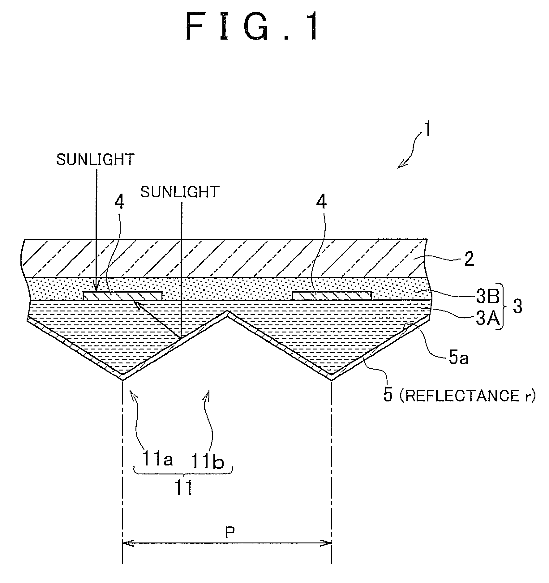
[0054]As shown in FIG. 4, the solar cell module is provided with a first encapsulant layer 30A. In the first encapsulant layer 30A, a flat surface 31, which is fixed to the solar cell 4, is provided with the second corrugated portion 10. However, an angular surface 32, which is fixed to a reflector 34, is not provided with the second corrugated portion 10.
[0055]The first encapsulant layer 30A, which is made of transparent polyethylene resin, may have the dimension of, for example, W1=12 mm, H1=4.8 mm, W2=0.4 mm, H2=0.3 mm, A=0.7 mm, and B=5.5 mm.
[0056]As shown in FIG. 5A, the reflector 34, which is fixed to the first corrugated portion 7 shown in FIG. 4, is provided with a metal substrate 35 made of aluminum, brass, stainless, etc. To the metal substrate 35, biaxially stretched polyethylene terephthalate film 37 that has deposited silver layer 36 is attached. To the deposited silver layer 36, a bonding layer 38 that is formed in the wavy shape by transparent light curing resin is a...
third embodiment
[0060]As shown in FIG. 6 and FIG. 7, in a solar cell module 50 a first encapsulant layer 51A of an encapsulant 55 includes a first corrugated portion 54 that corresponds to a corrugated portion 53 of a reflector 52. The corrugated portion 53 of the reflector 52 includes: two pairs of protrusions 53a and 53b that have a triangular cross section and that extend oppositely from the solar cell 4 at the both ends of the solar cell 4; a first groove 53c that is located between the protrusion 53a and the protrusion 53b and that is recessed toward the solar cell 4; and a second groove 53d that is located between the solar cells 4 and that has a triangular cross section.
[0061]As shown in FIG. 7, the first corrugated portion 54 of the first encapsulant layer 51A includes: a first protrusion 54a and a second protrusion 54b that correspond to the first protrusion 53a and the second protrusion 53b of the reflector 52 respectively; and a first groove 54c and a second groove 54d that correspond t...
fourth embodiment
[0065]As shown in FIG. 8 and FIG. 9, in a solar cell module 60 a first encapsulant layer 61A of an encapsulant 65 includes a first corrugated portion 64 that corresponds to a corrugated portion 63 of a reflector 62. The corrugated portion 63 of the reflector 62 includes: a groove 63b that is recessed in the trapezoidal shape toward the mono-facial solar cell 4A; and a protrusion 63a that is located between the mono-facial solar cells 4A and that has a triangular cross section.
[0066]As shown in FIG. 9, the first corrugated portion 64 of the first encapsulant layer 61A includes: a protrusion 64a that corresponds to the protrusion 63a of the reflector 62; and a groove 64b that corresponds to the groove 63b of the reflector 62. Since the solar cell 4A is a monofacial type, a bottom 63c of the reflector 62 faces the solar cell 4A in parallel. Correspondingly, a bottom 64c of the first encapsulant layer 61A faces the solar cell 4A in parallel.
[0067]In the first encapsulant layer 61A, the...
PUM
 Abstract
Description
Claims
Application Information