Device and method to prevent hip fractures

a technology for hip fractures and devices, applied in the field of devices and methods to prevent hip fractures, can solve the problems of increasing the quality of bone regions that are the subject of the greatest interest in the present application, increasing the cost of implants, so as to achieve the effect of preventing hip fractures

Active Publication Date: 2010-01-28
UNIV OF LOUISVILLE RES FOUND INC
View PDF41 Cites 33 Cited by
  • Summary
  • Abstract
  • Description
  • Claims
  • Application Information

AI Technical Summary

Benefits of technology

[0016]An exemplary device to prevent hip fractures in accordance with the present invention includes a shaft having a first end positioned in the femoral head and the second end positioned in the greater trochanter. The device is generally inserted through the lateral prominence of the greater trochanter of the femur along a generally horizontal axis that is substantially perpendicular to the long axis of the femoral shaft. The device further includes an expanding means for engaging the femoral head at the first end. As such, the device acts as a load-bearing (or load-sharing) device along or near the line of loading resulting from a fall to the side in which impact with the ground occurs over the greater trochanter of the lateral femur. In other words, the device interacts with and distributes the load occurring within the bone, such that the device shares the load occurring during a fall, thus preventing fracture.
[0018]Another exemplary device to prevent hip fractures in accordance with the present invention includes: a screw; a tubular structure defining a screw-receiving channel and having a first end and a second end; and an expanding means for engaging the femoral head that comprises a plurality of expanding molly bolt-like portions located near a first end. The screw has a threaded portion, and the screw-receiving channel includes corresponding and mating threads. Thus, the screw can be inserted into the tubular structure and received in the screw-receiving channel. When the device is inserted into a hole of a predetermined depth in a femur, the screw can be rotated such that the first end of the device is drawn toward the second end, effectively collapsing and forcing the plurality of molly bolt-like portions outward and into the surrounding bone.

Problems solved by technology

That being said, there is a common fear that putting a metal (e.g., titanium) implant in an otherwise normal (i.e., not fractured) femur to prevent hip fractures will result in bone loss around the implant due to the relative unloading of the bone from the load-sharing nature of the stiffer metal.
Thus, the bone region that is the subject of greatest interest in the present application is continually being diminished in quality by the natural processes of bone remodeling.
It is for this reason that natural or pharmacologic methods to augment the strength of bone often show poor results in preventing hip fractures as opposed to other fractures in other regions of the body.

Method used


Image

  • Device and method to prevent hip fractures
  • Device and method to prevent hip fractures
  • Device and method to prevent hip fractures

Examples


Embodiment Construction

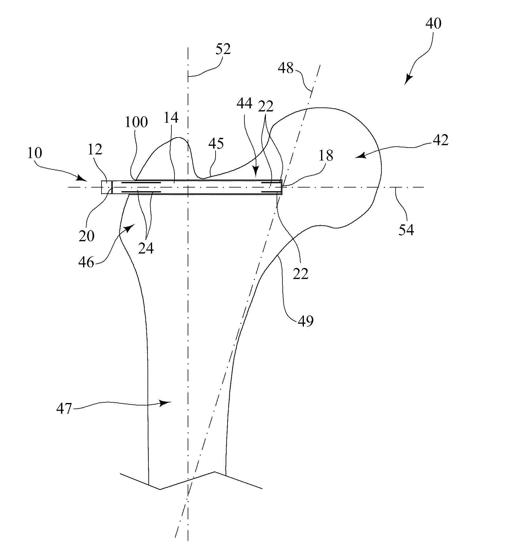
[0055]The present invention is a device and method to prevent hip fractures, and, more particularly, a device and method for preventing fractures along and in the region near the femoral neck without causing stress shielding.

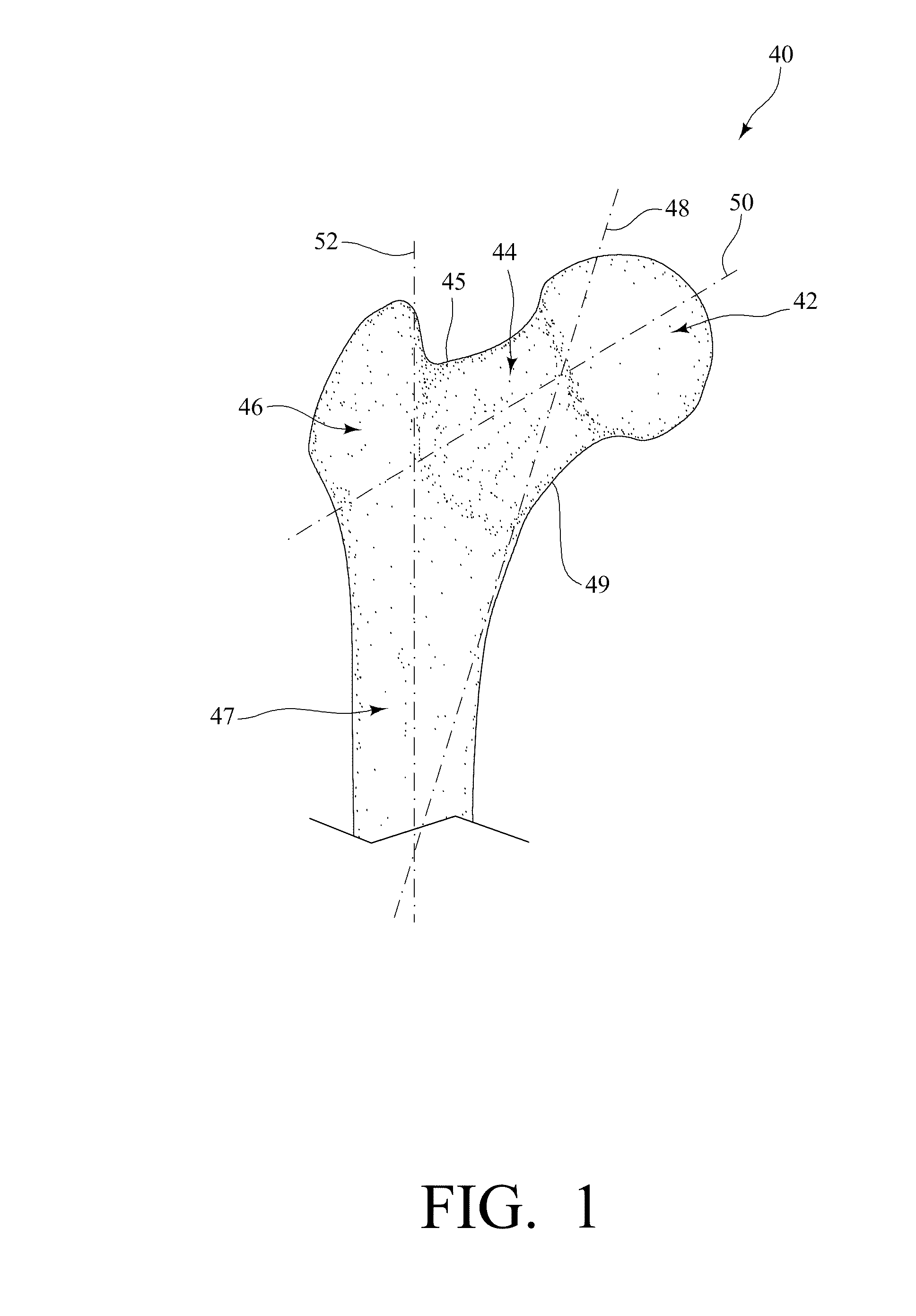
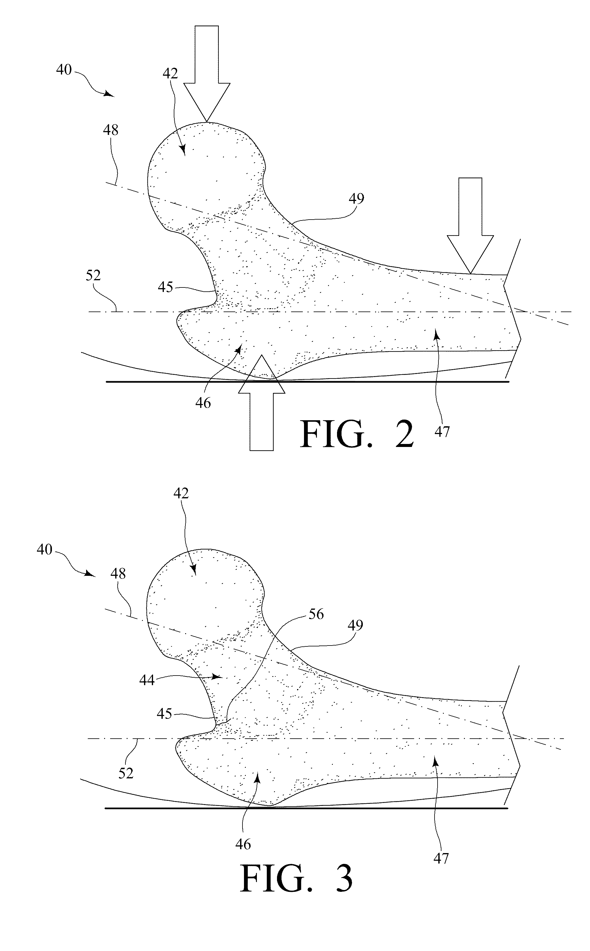
[0056]An exemplary device to prevent hip fractures made in accordance with the present invention includes a shaft having a first end positioned in the femoral head and the second end positioned in the greater trochanter. The device is generally inserted through the lateral prominence of the greater trochanter of the femur generally along a horizontal axis 54 that is substantially perpendicular to the long axis 52 of the femoral shaft 47. The device further includes an expanding means for engaging the femoral head 42 at the first end, as will be further discussed below. As such, the device acts as a load-bearing (or load-sharing) device along or near the line of loading resulting from a fall to the side in which impact with the ground occurs over the greater troc...


PUM


Abstract

A device for preventing a hip fracture includes: a shaft having a first end and a second end and an expanding means for engaging the femoral head at the first end. The shaft is positioned in a hole of a predetermined depth in a femur. The hole extends from the greater trochanter to the femoral head of the femur, such that the first end is positioned in the femoral head and the second end is positioned in the greater trochanter. The device is oriented substantially perpendicular to the long axis of the femoral shaft.

Description

CROSS-REFERENCE TO RELATED APPLICATIONS[0001]This application claims priority to U.S. Provisional Patent Application No. 61 / 082,848 filed on Jul. 23, 2008, the entire disclosure of which is incorporated herein by reference.BACKGROUND OF THE INVENTION[0002]The present invention relates to a device and method to prevent hip fractures.[0003]The femur is the longest and largest bone in the human body. The femur forms part of the hip at one end and part of the knee at the other end. FIG. 1 is a front view of the upper portion of a femur, illustrating the various parts or areas of the femur 40, including the femoral head 42, the femoral neck 44, and the greater trochanter 46.[0004]The femoral head 42 is generally globular and is directed upward, medialward, and a little forward, with the greater part of its convexity being above and in front. See Gray, Henry. Anatomy of the Human Body. Philadelphia: Lea & Febiger, 1918; Bartleby.com, 2000.[0005]The femoral neck 44 is a truncated conical p...

Claims


Application Information

Patent Timeline
Patent Type & Authority Applications(United States)
IPC IPC(8): A61B17/56
CPCA61B17/742A61B17/74A61F2/36A61F2/32
Inventor VOOR, MICHAEL J.
Owner UNIV OF LOUISVILLE RES FOUND INC
Why Eureka
Try Eureka