Sealed pipe joint

Inactive Publication Date: 2011-09-22
SINGLE BUOY MOORINGS INC
View PDF30 Cites 33 Cited by
  • Summary
  • Abstract
  • Description
  • Claims
  • Application Information

AI Technical Summary

Benefits of technology

[0007]The pipe ends include tongue and groove connections. To avoid one of the pipes fracturing at the outer side of the groove, the groove bottom is provided

Problems solved by technology

Previously, the opposite ends of a pipe sections could not both be tightly sealed, unless very high precision were used in the manufacture which results in p

Method used


Image

  • Sealed pipe joint
  • Sealed pipe joint
  • Sealed pipe joint

Examples


Embodiment Construction

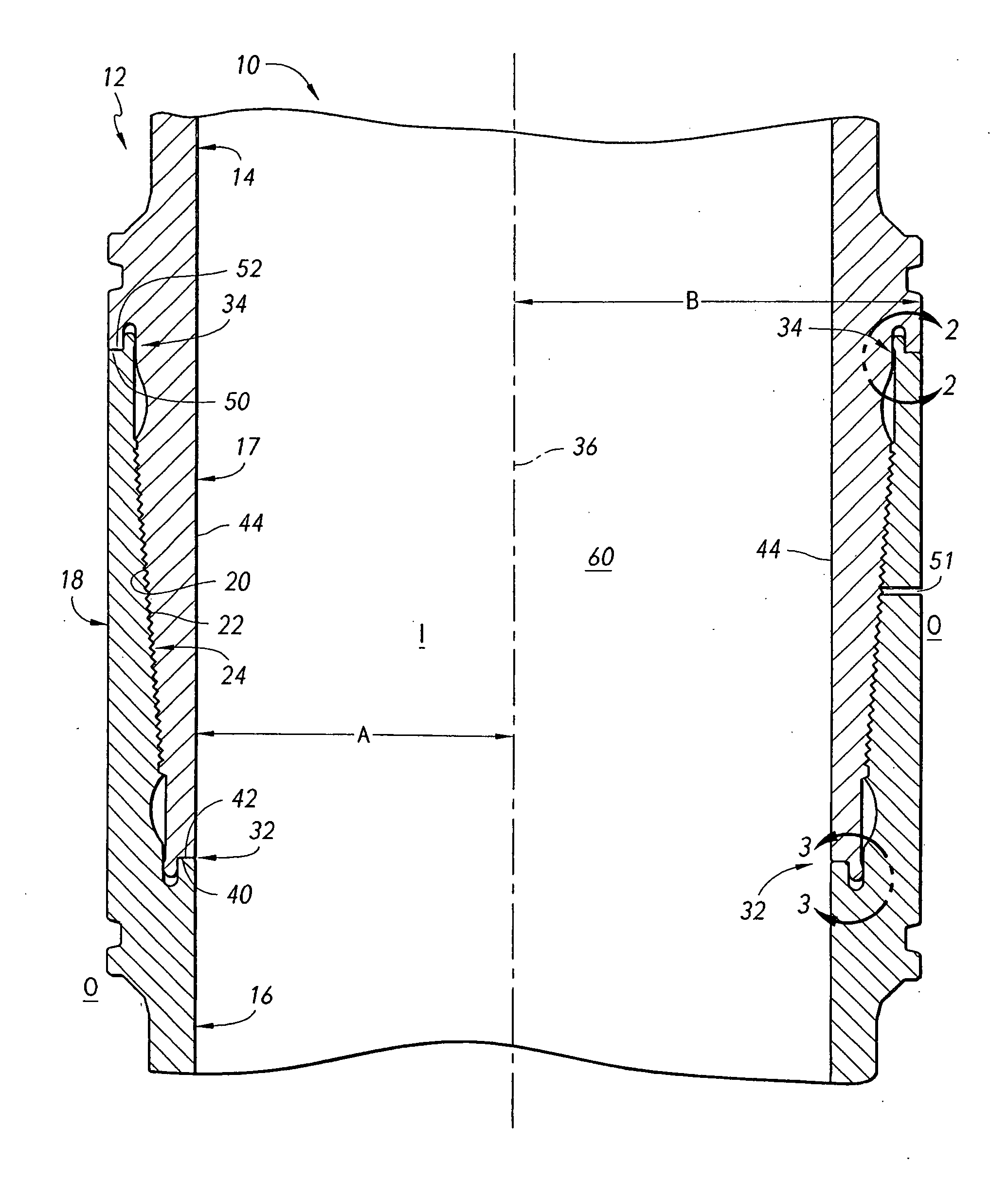
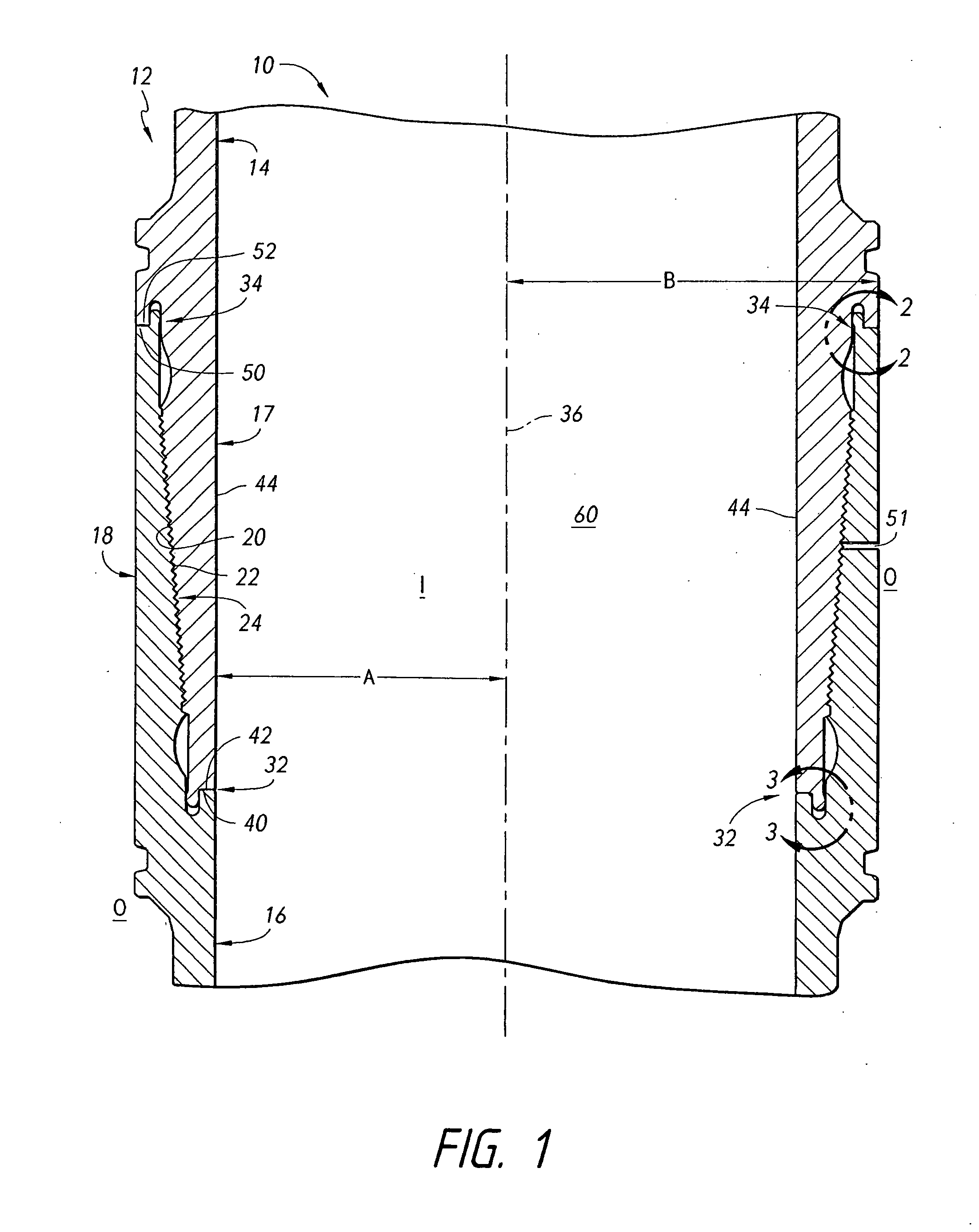
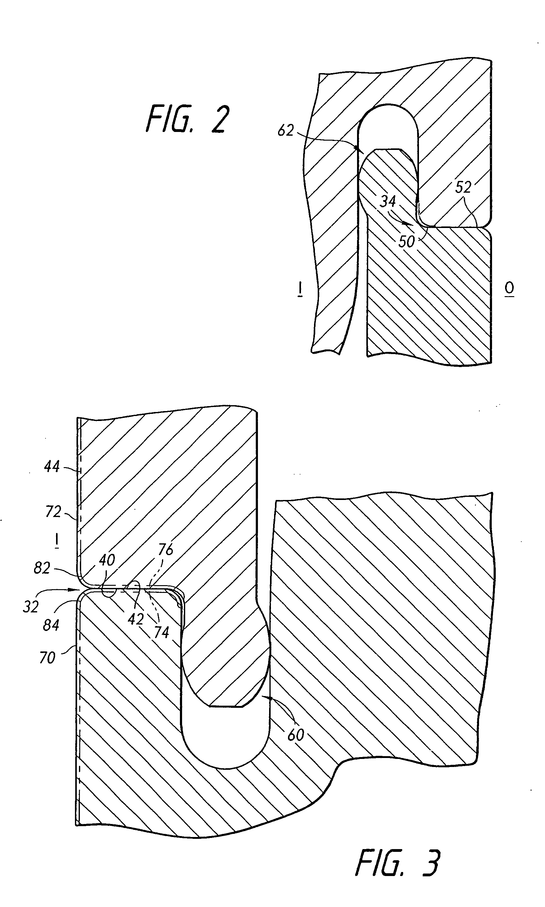
[0021]FIG. 1 shows a pipeline, or pipe string 10 that includes many steel pipe sections, each of a length such as 30 meters, which are threadably connected in tandem. Applicant notes that one type of threaded joint includes a helical thread, and another type includes axially-spaced (with respect to the pipeline axis) circular threads that lie on an imaginary cone. FIG. 1 shows a pipe joint 12 where adjacent end portions 17, 18 of two pipe sections 14, 16 are connected. The joint includes threads 2022 on the two pipe sections that form a threaded connection 24. The threads are tightened to press the two pipe ends close together at sealing surfaces 40, 42, 50, 52 that lie at axially (A) opposite joint ends 33, 34. To minimize thread chafing during a threadable connection applicant forms a port 51 in the radially (with respect to axis 36) outer pipe end 18. The joint can be pressurized by a fluid (liquid or gas) directed through the port 51, which compresses radially inner pipe end 17 ...


PUM

PropertyMeasurementUnit
Lengthaaaaaaaaaa
Lengthaaaaaaaaaa
Currentaaaaaaaaaa

Abstract

In a pipe joint where two pipe sections (14, 16) have threadably engaged end portions (17, 18), joint ends (32, 34) are substantially sealed to each other by a sealing surface (40, 50) on one pipe section that substantially abuts a sealing surface (42, 52) on the other pipe section. In one joint, a ring-shaped cutout (121, FIG. 7) is formed in a first pipe section and a ring-shaped spacer (120) is located in the cutout. The spacer is chosen from several that have slightly different lengths so the spacer end contacts the corresponding sealing surface (130). In a pipe string used to carry corrosive fluid, the inner surface (44) of adjacent pipe sections is covered with a corrosion resistant coating (70, 72). Where the sealing surface is connected to a rounded corner (82, 84), the coating extends to and along the sealing surfaces (40, 42). Where there are sharp corners (80) at the intersection of the inside surface (40) with the sealing surface (40B, 42B), the coating does not extend along the sealing surfaces.

Description

CROSS-REFERENCE[0001]Applicant claims priority from U.S. provisional patent application Ser. No. 61 / 316,371 filed 22 Mar. 2010.BACKGROUND OF THE INVENTION[0002]Pipe strings consisting of many pipe sections connected in tandem, are widely used in the sea to transfer crude oil and other hydrocarbons between the sea floor and a floating body, or between floating bodies. One common type of pipe string includes many steel pipe sections, each of a length such as 30 meters, that are connected together by threaded end portions lying at opposite ends of each pipe. Applicant notes that one type of thread is a helical thread, and another type includes axially-spaced circular threads. Each end of a pair of adjacent pipe sections is preferably sealed to the other pipe section by a sealing surface on the end of one pipe section that presses against a sealing surface on the end of the other pipe section as the pipe section are threaded together. Previously, the opposite ends of a pipe sections cou...

Claims


Application Information

Patent Timeline
IPC IPC(8): F16L15/04F16L15/06F16L15/08B23P17/04
CPCY10T29/49826F16L15/004E21B17/042
Inventor POLLACK, JACKRIGGS, DAVID C.
Owner SINGLE BUOY MOORINGS INC
Why Eureka
Try Eureka