Fracture Prediction Device For Spot Welded Portion, Method Of The Same, Computer Program, And Computer Readable Recording Medium

a prediction device and spot welding technology, applied in the field of spot welding portion fracture prediction device, can solve the problems of long design time, high manufacturing cost, and deterioration of impact energy, and achieve the effect of improving the absorbed energy of the crash

Active Publication Date: 2007-08-30
NIPPON STEEL CORP
View PDF1 Cites 32 Cited by
  • Summary
  • Abstract
  • Description
  • Claims
  • Application Information

AI Technical Summary

Benefits of technology

[0012] One of the objects of the present invention is to prevent the fracture of the welded portion of the member at the time of crash deformation, to thereby realize an optimization of a deformed buckling mode. Another object of the present invention is to improve the absorbed energy of the crash by determining a

Problems solved by technology

Recently, it became problematic for an automotive industry to develop a vehicle structure that is capable of eliminating or significantly reducing an injury for a passenger at a time of a collision.
There may exist certain problems such as a fracture which may occur from a welded point at the time of buckling to cause an unstable buckling mode and the absorption of the impact energy deteriorates, if a spot welding interval, a nugget diameter, and a welding condition are not optimized to stabilize the buckling as for the above-stated spot welding of the member.
However, in the above-described method, trial and error should be used in which experimental products are manufactured by each automobile, or by each member to perform the test.
Therefore, a problem may exist such that a manufacturing cost becomes high and a long time for design.
Therefore, it still required trial and error by the exp

Method used


Image

  • Fracture Prediction Device For Spot Welded Portion, Method Of The Same, Computer Program, And Computer Readable Recording Medium
  • Fracture Prediction Device For Spot Welded Portion, Method Of The Same, Computer Program, And Computer Readable Recording Medium
  • Fracture Prediction Device For Spot Welded Portion, Method Of The Same, Computer Program, And Computer Readable Recording Medium

Examples


example 1

[0059] An exemplary embodiment of a system is according to the present invention can be structured in which the above-stated fracture prediction model is used, and a fracture of a spot welded portion is judged automatically while analyzing a collision deformation of a member, as a subroutine program in a general collision analysis FEM code. The used code is “PAM-CRASH v2002” made by ESI Co., Ltd., and the spot welded portion is modeled by using a “Multi-PLINK” as for the member modeled by a shell element.

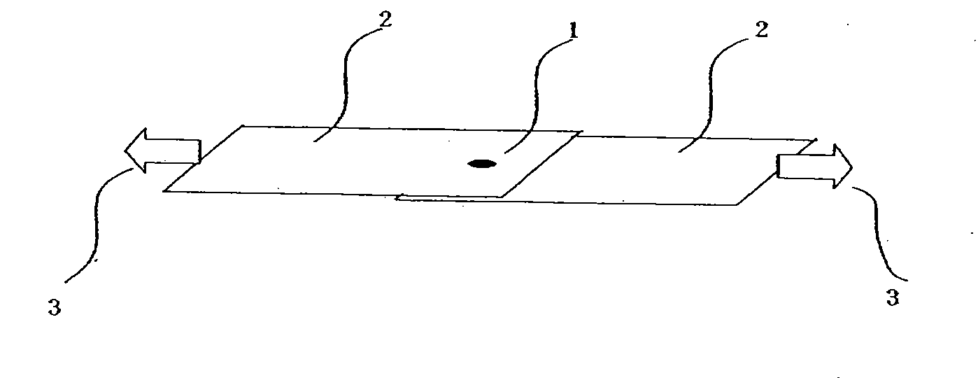
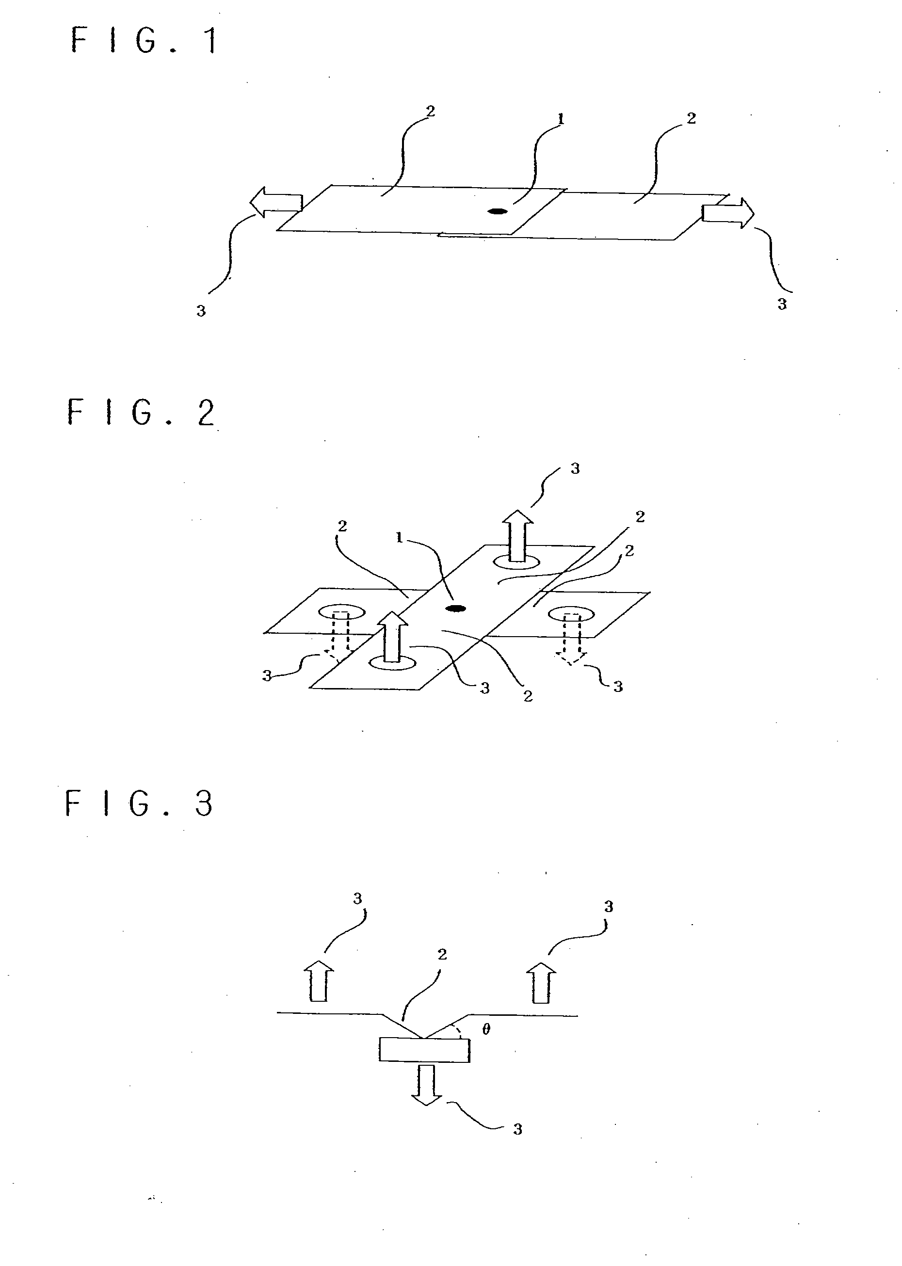
[0060] A comparison of an analysis, in which a shear tension test and a cross tension test are modeled as they are, and an experiment is the best for an accuracy verification of the fracture prediction model, because an exact comparison becomes possible. Therefore, a shear tension specimen and a cross tension specimen are created with a steel plate of 590 MPa grade and a thickness “t”=1.8 (mm), according to JIS standards of 3136, 3137. A nugget diameter of the spot welding is 5√t (...

example 2

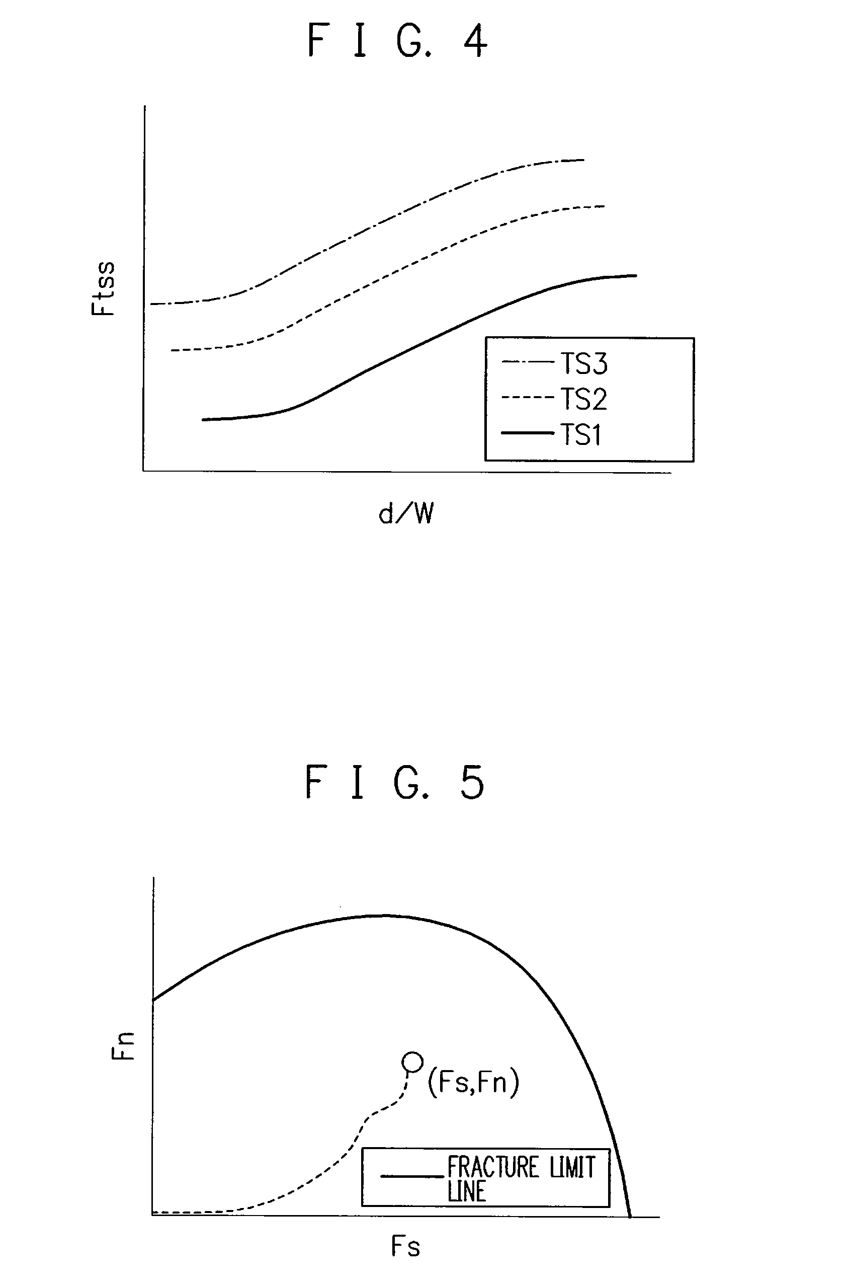
[0067] A verification of a prediction accuracy of a shear tensile strength is performed by using a fracture strength curve. Material thereof can be a steel plate of 590 MPa grade, a thickness=1.8 (mm) as same as described in Example 1. Initially, a width “W” of a specimen of the shear tension test can be varied from 20 (mm) to 50 (mm), at the same time, a nugget diameter “d” is also varied from 4 (mm) to 7 (mm) to perform the test, and a fracture strength parameter “Ftss” is actually measured. An exemplary fracture strength curve shown in FIG. 9 can be obtained from the results of the test. The fracture strength parameter “Ftss”=25.5 (kN) can be read from the fracture strength curve as shown by a circular sign in FIG. 9, under a condition of “d”=6.7 (mm), “W”=40 (mm) which is the same condition as in the example 1. This is approximately the same value with the “Ftss” under the same condition in the example 1. The fracture loads are generally matched on the load—stroke curves of the ...

example 3

[0068] In addition, an exemplary system can be structured such that a fracture prediction model when a tensile strength thereof is larger than 590 MPa grade is used, and a fracture of a spot welded portion is automatically judged while analyzing a collision deformation of a member as a subroutine program in the general collision analysis FEM code. The used code is “PAM-CRASH v2003” made by ESI Co., Ltd., and the spot welded portion of a member which is modeled by a shell element is modeled by using “Multi-PLINK”.

[0069] A comparison of an analysis, in which the shear tension test can be modeled as is, and an experiment is preferable for an accuracy verification of the fracture prediction model, because an exact comparison becomes possible. Therefore, a shear tension specimen can be created with a steel plate of 980 MPa grade and a thickness “t”=1.4 (mm) as same as in the example 1. A nugget diameter of the spot welding is 6√t (mm). A test may be performed using an Instron type testi...


PUM

PropertyMeasurementUnit
Thicknessaaaaaaaaaa
Strengthaaaaaaaaaa
Fractureaaaaaaaaaa

Abstract

According to exemplary embodiments of the present invention, a fracture prediction device for a spot welded portion can be provided. For example, the device may include an input arrangement configured to input all or some of a material strength, a plate thickness, a nugget diameter of a spot welding, a plate width of a joint, and a rotation angle of the joint in a tension test, based on a cross tension test and/or a shear tension test at a spot welded joint. The device can also include a first calculation arrangement configured to calculate a fracture strength parameter of the spot welded portion from all or any of the material strength, the plate thickness, the nugget diameter of the spot welding, the plate width of the joint, and the rotation angle of the joint in the tension test. A parameter storage arrangement may also be provided which can be configured to store the fracture strength parameter by each steel type. Further, the device may further have a second calculation arrangement configured to determine a fracture of the spot welded portion by installing the fracture strength parameter stored in the parameter storage arrangement into a fracture prediction formula in which a deformation at a periphery of the spot welding is modeled by a finite element procedure. Exemplary embodiments of the method software arrangement and computer accessible medium performing similar procedures can also be provided.

Description

CROSS-REFERENCE TO RELATED APPLICATION(S) [0001] This application is a national stage application of PCT Application No. PCT / JP2005 / 007100 which was filed on Apr. 12, 2005 and published on Oct. 27, 2005 as International Publication No. WO 2005 / 100949, the entire disclosure of which is incorporated herein by reference. This application claims priority from the International Application pursuant to 35 U.S.C. § 365. The present application also claims priority under 35 U.S.C. § 119 from Japanese Patent Application Nos. 2004-118201 and 2005-112644, filed Apr. 13, 2004 and Apr. 8, 2005, respectively.FIELD OF THE INVENTION [0002] The present invention relates to a fracture prediction device for a spot welded portion, suitable for use for a spot welding of a structural member for an automobile, and in particular, for predicting a fracture of the spot welded portion of a member at a time of a collision deformation, to a method thereof, a software arrangement (e.g., a computer program), and ...

Claims


Application Information

Patent Timeline
IPC IPC(8): B23K11/25G01N3/00B23K11/11B23K11/24G01M7/08G01N3/08G01N3/24G06F17/50
CPCB23K11/11G01N3/08G01N3/24G06F17/5018G01N2203/0216G01N2203/0218G01N2203/0296G01N2203/0214G01N2203/0067G06F30/23B23K11/24G01N3/00
Inventor YOSHIDA, HIROSHINOMURA, NARUHIKOUENISHI, AKIHIRO
Owner NIPPON STEEL CORP
Why Eureka
Try Eureka