
Refrigerant distributing component, header assembly, and heat exchanger

a technology of refrigerant distribution and heat exchanger, which is applied in the direction of refrigeration components, indirect heat exchangers, lighting and heating apparatus, etc. it can solve the problems of uneven distribution of refrigerants into each flat tube of the heat exchanger, and the inability to distribute refrigerants evenly into each flat tube, so as to facilitate a more even distribution of refrigerants and reduce the vapour-liquid separation phenomenon. , the effect of improving the homogeneity

Active Publication Date: 2016-07-21
SANHUA HANGZHOU MICRO CHANNEL HEAT EXCHANGER
View PDF1 Cites 4 Cited by
  • Summary
  • Abstract
  • Description
  • Claims
  • Application Information

AI Technical Summary

Benefits of technology

This patent is about a new refrigerant distributing component and header assembly that can reduce the separation of vapor and liquid in the refrigerant. The refrigerants sprayed from different parts of the distributing holes collide with each other, which creates a strong disturbance and helps the two-phase refrigerants mix evenly. This improves the distribution of the refrigerants in the heat exchanger, reducing the vapor-liquid separation and improving the performance of the heat exchanger. Overall, this patent aims to enhance the efficiency and performance of heat exchangers.

Problems solved by technology

A vapour-liquid separation occurs to the refrigerants in a distributing device, and refrigerants sprayed from one part of the distributing holes are all liquids and refrigerants sprayed from another part of the distributing holes are all vapours, resulting in an uneven distribution of the refrigerants entering each flat tube of the heat exchanger.
Moreover, after the refrigerants with two phases of vapour and liquid flow through the distributing holes, a vapour-liquid separation phenomenon may also be caused by a difference in density of the refrigerants in vapour and liquid phase, thus the refrigerants cannot be distributed into each flat tubes evenly.

Method used


Image

  • Refrigerant distributing component, header assembly, and heat exchanger
  • Refrigerant distributing component, header assembly, and heat exchanger
  • Refrigerant distributing component, header assembly, and heat exchanger

Examples


Embodiment Construction

[0056]Embodiments of the present disclosure will be described in detail and examples of the embodiments will be illustrated in the drawings, where same or similar reference numerals are used to indicate same or similar members or members with same or similar functions. The embodiments described herein with reference to drawings are explanatory, which are used to illustrate the present disclosure, but shall not be construed to limit the present disclosure.

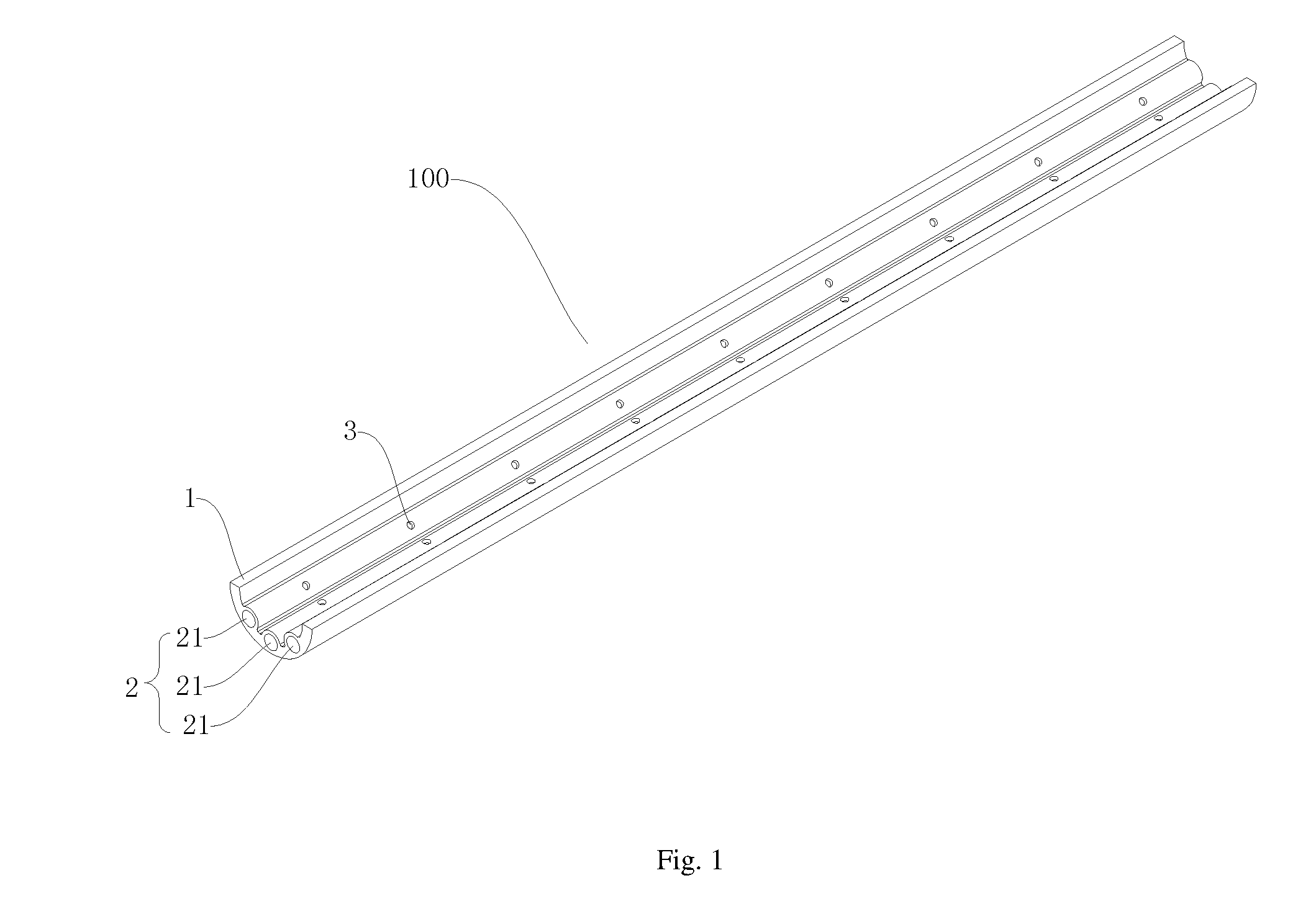
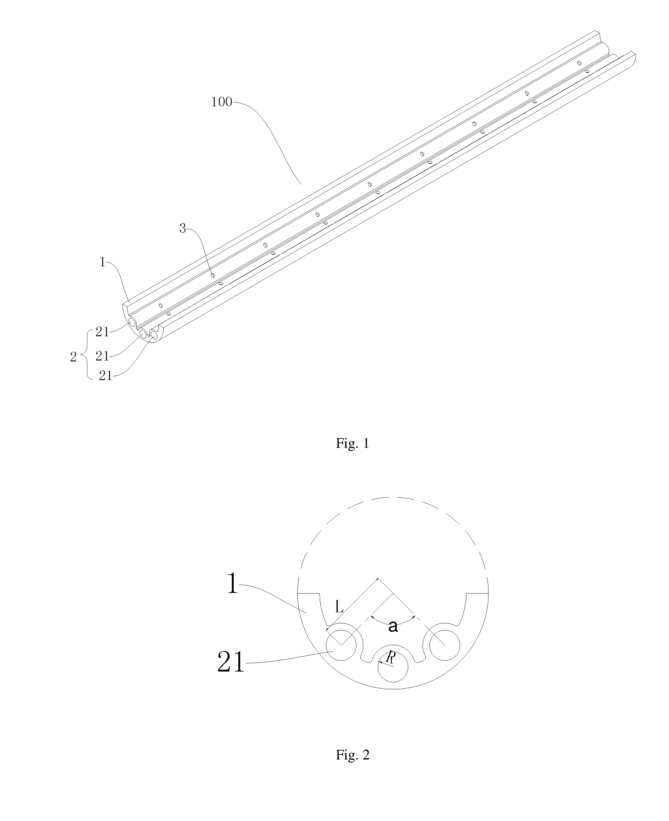
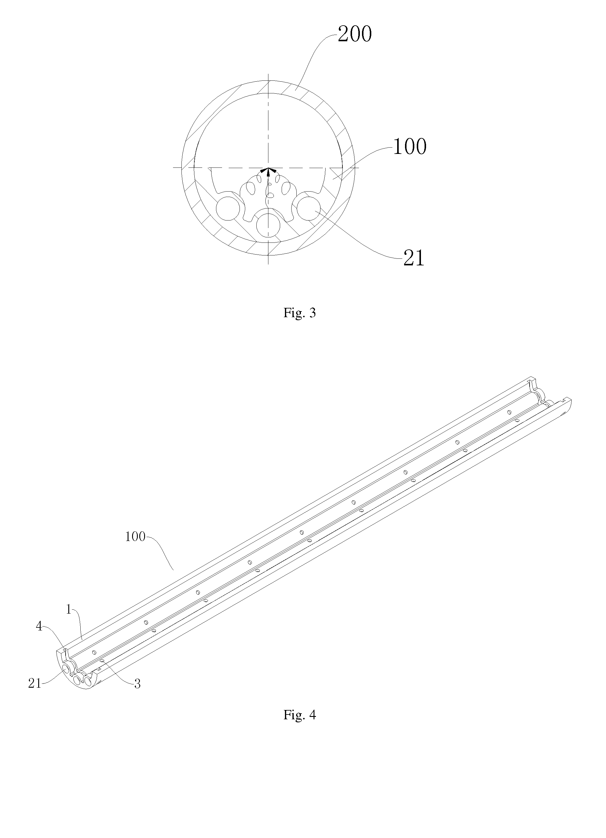
[0057]A refrigerant distributing component 100 according to embodiments of the present disclosure is described with reference to FIG. 1 to FIG. 11. The refrigerant distributing component 100 is disposed in a header of a heat exchanger and used to distribute the refrigerant to the header, so that the refrigerant can be distributed evenly among heat exchanging tubes of the heat exchanger.

[0058]As shown in FIG. 1 to FIG. 11, the refrigerant distributing component 100 according to embodiments of the present disclosure includes a body 1 ...


PUM


Abstract

A refrigerant distributing component includes a body. The body has a distributing cavity extending along a length direction of the body therein and an inner sidewall of the distributing cavity has a plurality of distributing hole therein, wherein refrigerants sprayed from one part of the distributing holes collide with refrigerants sprayed from another part of the distributing holes.

Description

CROSS-REFERENCE TO RELATED APPLICATION[0001]This application is a U.S. National Phase application of the International Patent Application No. PCT / CN2014 / 070743, filed Jan. 16, 2014, which claims the benefit of prior Chinese Application No. 201310378731.5 filed Aug. 27, 2013. The entire contents of the above-mentioned patent applications are incorporated by reference as part of the disclosure of this U.S. application.BACKGROUND OF THE INVENTION[0002]1. Field of the Invention[0003]The present disclosure relates to a field of refrigeration technology, and more particularly to a refrigerant distributing component, a header assembly and a heat exchanger.[0004]2. Description of the Related Art[0005]In order to improve performances of a heat exchanger, a refrigerant distributing component is normally disposed in the header of the heat exchanger, e.g., a circular tube having distributing holes in a wall thereof. When the heat exchanger is used as an evaporator or an outdoor heat pump, the r...

Claims


Application Information

Patent Timeline
Patent Type & Authority Applications(United States)
IPC IPC(8): F25B39/00F28F9/02
CPCF25B39/00F28F9/0273F25B39/028F28F9/0202F28F9/0275F28F9/0265F28F9/0278F28F9/028F28D1/05366F28F1/126F28F2255/16
Inventor ZHOU, JINGHE, YANLIU, HUAZHAOGAO, QIANG
Owner SANHUA HANGZHOU MICRO CHANNEL HEAT EXCHANGER
Learn More