
Projection screen apparatus, projection apparatus, and projection method

a projection screen and projection screen technology, applied in the field of projection screen apparatus, can solve the problems of negligible personal injury risk during/after breakage/fragmentation of the display panel, and achieve the effects of preventing multiple reflections, improving the recognizability of at least one displayed image symbol, and increasing the transmittan

Active Publication Date: 2016-07-21
ROBERT BOSCH GMBH
View PDF5 Cites 4 Cited by
  • Summary
  • Abstract
  • Description
  • Claims
  • Application Information

AI Technical Summary

Benefits of technology

The present invention creates a display panel that can project a clear and speckle-free image onto the screen. This is achieved by creating a uniform oscillating motion to the diffuser screen, which reduces the speckle of the light projected onto the screen. The invention also prevents the occurrence of a double image and multiple reflections, which can improve the image quality and readability of the displayed image. The use of a viscoelastic filler material in the gap between the display panel and the actuator device ensures the desired damped amplitude of the oscillating motion, and also prevents any risk of personal injury during breakage of the display panel. The use of the display panel in a vehicle interior or as an external component of a combination instrument is also possible, and the use of an inexpensive glass material for the display panel is also possible. The at least one viscoelastic filler material used in the invention is transparent to wavelengths in the visible range, and its refractive index matches that of the display panel to prevent double image or multiple reflection. The actuator device used in the invention is easy and inexpensive to manufacture.

Problems solved by technology

A risk of personal injury during / after breakage / fragmentation of the display panel is thus negligibly low.

Method used


Image

  • Projection screen apparatus, projection apparatus, and projection method
  • Projection screen apparatus, projection apparatus, and projection method
  • Projection screen apparatus, projection apparatus, and projection method

Examples


first embodiment

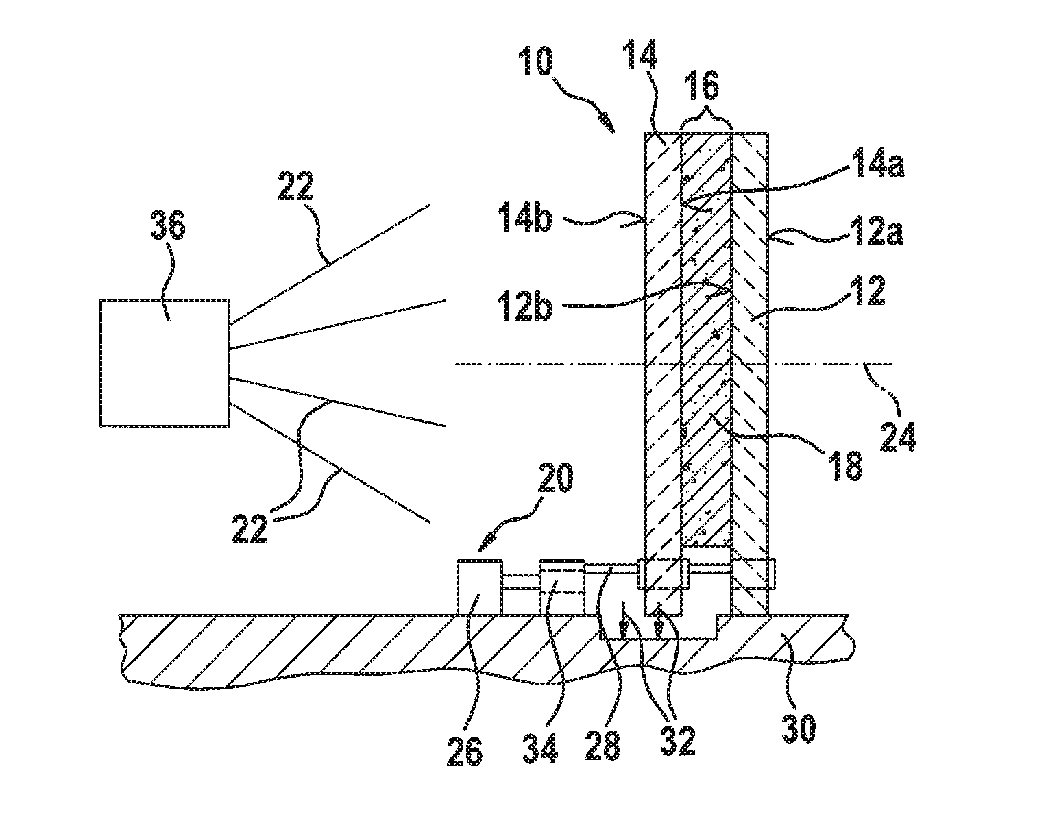
[0019]FIG. 1 schematically depicts the projection screen apparatus.

[0020]Projection screen apparatus 10 (e.g. a projection screen or display screen) depicted schematically in FIG. 1 has a display panel 12 having an external panel surface 12a and an internal panel surface 12b. Panel surfaces 12a and 12b of display panel 12 can be understood in particular as the two maximal (external) surfaces of display panel 12. In the embodiment of FIG. 1, external panel surface 12a and internal panel surface 12b are each smooth. Display panel 12 can be embodied in particular as a “smooth” panel, for example as a parallelepipedal panel or as a cylindrical panel. Further possibilities for the shape of display panel 12 are described below.

[0021]Display panel 12 can be, in particular, a glass panel (made, especially, of an inexpensive glass material). It is noted, however, that any material transparent to wavelengths in the visible range is usable for manufacturing display panel 12. The range of embod...

second embodiment

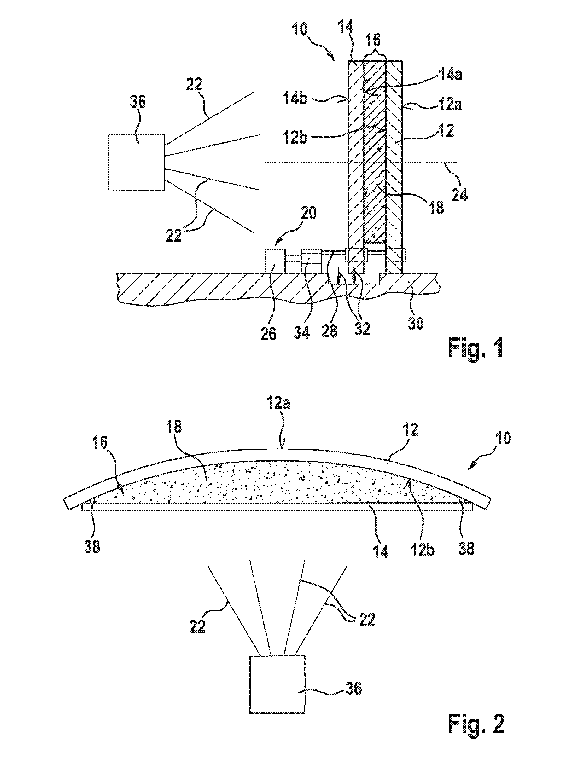
[0035]FIG. 2 schematically depicts the projection screen apparatus.

[0036]As is evident in FIG. 2, display panel 12 can have at least one rounded external panel surface 12a. Display panel 12 of FIG. 2 can furthermore have both a rounded external panel surface 12a and a rounded internal panel surface 12b. Display panel 12 can be externally and / or internally rounded, but an external and internal rounding of display panel 12 is optional.

[0037]In the embodiment of FIG. 2, the oscillating motion with respect to display panel 12 is impartable to diffuser screen 14 by way of the actuator device (not depicted) in such a way that a distance between diffuser screen 14 and display panel 12 is periodically variable. The actuator device can have, for example, at least one piezo. Optionally, at least one edge joint 38, which frames the at least one filler material 18, can be embodied on display panel 12 and / or on diffuser screen 14. Undesired discharge of the at least one filler material 18 is rel...


PUM


Abstract

A projection screen apparatus has: a display panel having an external panel surface and an internal panel surface; an actuator device by way of which an oscillating motion is impartable to at least a part of the projection screen apparatus; a diffuser screen, disposed adjacently to the internal panel surface, to which the oscillating motion with respect to the display panel is imparted by way of the actuator device; and a gap between the internal panel surface of the display panel and an inner surface of the diffuser screen directed toward the internal panel surface being filled at least in part with at least one viscoelastic filler material.

Description

BACKGROUND OF THE INVENTION[0001]1. Field of the Invention[0002]The present invention relates to a projection screen apparatus. The invention likewise relates to a projection apparatus. The invention furthermore relates to a projection method.[0003]2. Description of the Related Art[0004]US Patent Application Publication 2013 / 0010356 A1 describes a display screen and an apparatus interacting therewith. The entire display screen is intended to have vibrations imparted to it by way of the apparatus in such a way that when an image is simultaneously projected onto the display screen, an occurrence of a granularity, which is also often referred to as “speckle,” is suppressed. For example, the entire display screen has vibrations, in particular a resonant oscillation, imparted to it by the emission of sound waves by way of the apparatus.BRIEF SUMMARY OF THE INVENTION[0005]The present invention creates capabilities for projecting a clear and speckle-free image onto the display panel. Thank...

Claims


Application Information

Patent Timeline
Patent Type & Authority Applications(United States)
IPC IPC(8): G02B27/48G02B5/02G03B21/56
CPCG02B27/48G02B5/0278G03B21/562G03B21/608
Inventor DIGEL, TOBIASLUBENOW, CEDRICFISCHER, FRANKEDEL, MARTIN
Owner ROBERT BOSCH GMBH
Learn More