Inverter controller and control method of inverter device

a technology of inverter controller and control method, which is applied in the direction of dynamo-electric converter control, pulse technique, motor/generator/converter stopper, etc., can solve the problems of erroneous operation of the device, dielectric breakdown, and loss of switching element, so as to reduce the switching loss, reduce the surge voltage, and reduce the switching speed of the switching element

Inactive Publication Date: 2016-07-21
TOYOTA JIDOSHA KK
View PDF1 Cites 19 Cited by
  • Summary
  • Abstract
  • Description
  • Claims
  • Application Information

AI Technical Summary

Benefits of technology

[0012]The invention provides an inverter controller that can actively reduce a surge voltage while appropriately suppressing a switching loss and a control method of an inverter device.

Problems solved by technology

Since the operation of a switching element is used in the inverter device, a switching loss determined by the integration of the product of the voltage drop and the current of the switching element is caused between switching times such as a turn-on time and a turn-off time.
The generated surge voltage may affect insulation of a stator coil of a motor or an element withstand voltage and may also serve to cause an erroneous operation of a device.
At this time, when the dielectric strength between the coils is not sufficient, dielectric breakdown occurs between the coil conductors adjacent to each other in the same phase to which the surge voltage is applied.
There is a possibility that failure such as vehicle stoppage occurs when the dielectric breakdown occurs and a large current flows in the motor.
In order to prevent the dielectric breakdown between the coil conductors, it can be considered that an insulating resin of the coil be replaced with a resin configured to withstand high voltage or be increased in thickness with respect to a present level of a surge voltage, but this method may increase the cost or may cause the size of the motor to increase.
However, in this method, since the switching time increases, the switching loss increases to lower energy efficiency and to degrade fuel efficiency, for example, in a vehicle.
When the switching loss increases, an amount of heat emitted also increases.
Accordingly, when an insulating material having a high temperature specification is selected so that the temperature of the switching element does not rise above a guaranteed heat-resistance temperature, the cost increases.

Method used


Image

  • Inverter controller and control method of inverter device
  • Inverter controller and control method of inverter device
  • Inverter controller and control method of inverter device

Examples


Embodiment Construction

[0033]An embodiment of the invention will be described below with reference to the accompanying drawings.

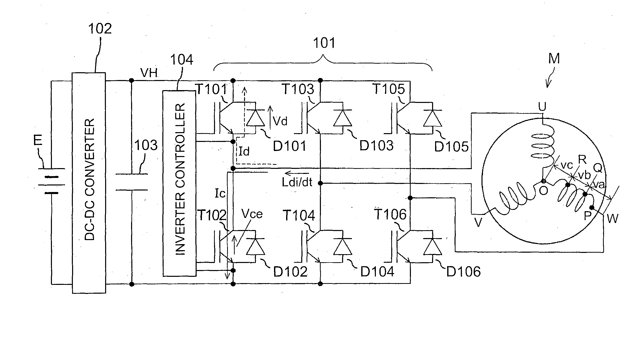
[0034]First, a recovery surge voltage generated in an inverter device will be described below. FIG. 4 illustrates a configuration example of a voltage inverter that generates AC power to be supplied to a three-phase AC motor for running a vehicle. The inverter device 101 includes switching elements T101 to T106 and reflux diodes D101 to D106. Each of the switching elements T101 to T106 may be an insulated gate bipolar transistor (IGBT) and so on. The output voltage of a battery E is boosted by a DC-DC converter 102 and is smoothed by an input capacitor 103. An inverter controller 104 uses a voltage between terminals of the input capacitor 103 as an input and generates phase voltages of a motor M, for example, by turning on and off the switching elements T101, T103, and T105 of an upper arm and the switching elements T102, T104, and T106 of a lower arm in the respective legs of a ...


PUM


Abstract

An inverter controller is configured to control an inverter device. The inverter device is configured to generate a drive voltage of an AC load by a switching operation of a switching element that a reflux diode is connected to. The inverter controller is configured to perform a control of setting a switching speed of the switching element to be smaller on a lower level side of a magnitude of a current flowing in the AC load than on a higher level side of the magnitude of the current.

Description

BACKGROUND OF THE INVENTION[0001]1. Field of the Invention[0002]The present invention relates to control of an inverter device that generates power to be supplied to an AC load by switching an output of a DC power supply.[0003]2. Description of Related Art[0004]An inverter device that generates a single-phase or multi-phase AC voltage to be supplied to various power loads such as a vehicle-running motor by switching a DC source voltage has been widely used. Since a waveform to be output from the inverter device to an AC load can be controlled as desired by a controller that drives the inverter device, an output-variable control corresponding to a load state can be performed.[0005]Since the operation of a switching element is used in the inverter device, a switching loss determined by the integration of the product of the voltage drop and the current of the switching element is caused between switching times such as a turn-on time and a turn-off time. Since the switching loss becomes...

Claims


Application Information

Patent Timeline
Patent Type & Authority Applications(United States)
IPC IPC(8): H02M7/537H02P27/06H02M1/00H02M7/48
CPCH02P27/06H02M7/537H02M1/08H03K17/14H03K17/163H02P29/0241H02P29/032H02M1/0029
Inventor HOTTA, NORIHISA
Owner TOYOTA JIDOSHA KK
Why Eureka
Try Eureka