Power module, power converter, and electric machine system for mounting in vehicle

a technology of power converter and power module, which is applied in the direction of motor/generator/converter stopper, dynamo-electric converter control, propulsion by batteries/cells, etc., can solve the problem of too high inductance on the periphery of output terminal for sufficient surge voltage reduction, etc. problem, to achieve the effect of reducing surge voltage, reducing inductance, and reducing inductan

Active Publication Date: 2009-08-04
HITACHI ASTEMO LTD
View PDF4 Cites 8 Cited by
  • Summary
  • Abstract
  • Description
  • Claims
  • Application Information

AI Technical Summary

Benefits of technology

[0007]An object of the present invention is to provide a power module, power converter, and vehicular electric machine system capable of reducing inductance which occurs particularly on a peripheral section of an output terminal in a power module, and at the same time, reducing a surge voltage.
[0008]The present invention makes it possible to reduce inductance that occurs on a peripheral section of an output terminal in a power module, and at the same time, reduce a surge voltage.

Problems solved by technology

The power module described in JP-A-2001-274322, however, has had the problem that since the current path ranging from the emitter electrode of the positive IGBT chip to the output terminal is too long, the inductance that occurs on the periphery of the output terminal is too high for sufficient reduction in the surge voltage.

Method used


Image

  • Power module, power converter, and electric machine system for mounting in vehicle
  • Power module, power converter, and electric machine system for mounting in vehicle
  • Power module, power converter, and electric machine system for mounting in vehicle

Examples


first embodiment

[0023]A configuration of a power module, power converter, and vehicular electric machine system according to the present invention is described below by using FIGS. 1 to 4.

[0024]In the embodiment described below, an inverter for mounting in a vehicle is taken as an example of a power converter in which the power module of the present invention is used. The inverter controls driving of a motor mounted in the vehicle, and is adapted to convert DC power supplied from a battery which is mounted in the vehicle and constitutes a power supply mounted in the vehicle, into AC power and supply the thus-obtained AC power to the motor.

[0025]The configuration described below can also be applied to DC-DC power converters such as DC choppers. In addition, the configuration described below can be applied to power converters for industrial, household, and other purposes.

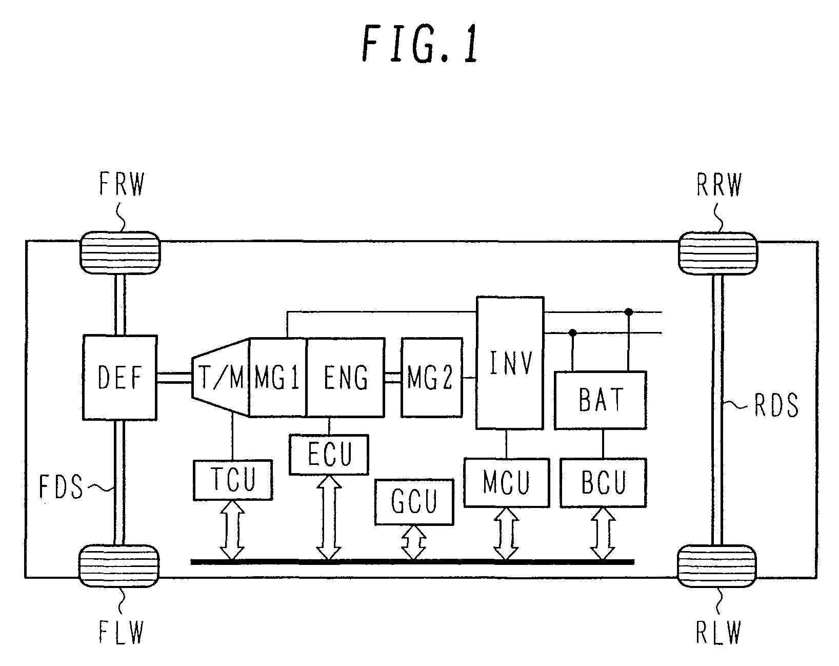
[0026]First, a configuration of a vehicle having the vehicular electric machine system according to the present embodiment is descr...

second embodiment

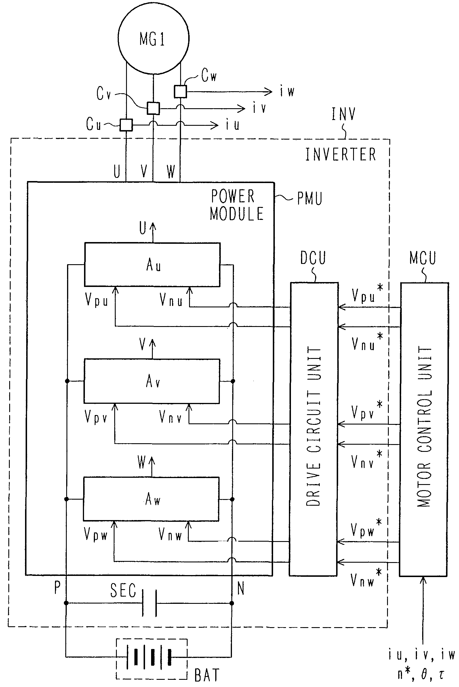
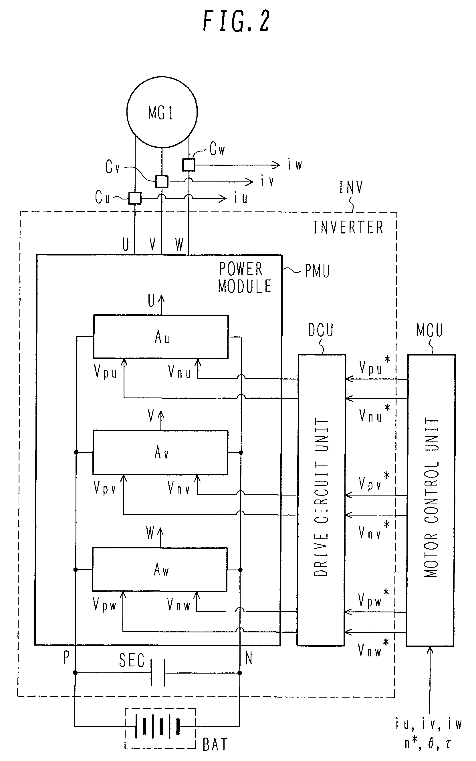
[0099]Next, circuit composition of a power module according to the present invention is described below by using FIG. 5. A configuration of a vehicle with a vehicular electric machine system according to the present embodiment is essentially the same as the configuration shown in FIG. 1. Also, circuit composition of an inverter INV in the vehicular electric machine system according to the present embodiment is essentially the same as the composition shown in FIG. 2.

[0100]FIG. 5 is a plan view showing a configuration of a U-phase (V-phase, W-phase) arm “Au” (“Av”, “Aw”) of the power module PMU used in the vehicular electric machine system of the present embodiment. The same reference numbers and symbols as used in FIGS. 1 to 4 denote the same elements.

[0101]In the present embodiment, a positive collector conductor 2, a positive emitter conductor 3, a negative collector conductor 4, and a negative emitter conductor 5 are solder-bonded onto a dielectric substrate 1. That is to say, whe...

third embodiment

[0106]Next, circuit composition of a power module according to the present invention is described below using FIG. 6. A configuration of a vehicle with a vehicular electric machine system according to the present embodiment is essentially the same as the configuration shown in FIG. 1. Also, circuit composition of an inverter INV in the vehicular electric machine system according to the present embodiment is essentially the same as the composition shown in FIG. 2.

[0107]FIG. 6 is a plan view showing a configuration of a U-phase (V-phase, W-phase) arm “Au” (“Av”, “Aw”) of the power module PMU used in the vehicular electric machine system of the present embodiment. The same reference numbers and symbols as used in FIGS. 1 to 5 denote the same elements.

[0108]The present embodiment differs from the embodiment of FIG. 3 in that a positive emitter conductor and a negative collector conductor are integrated into one conductor pattern formed as an emitter-collector conductor pattern 13. In th...


PUM


Abstract

The present invention provides a power module, power converter, and vehicular electric machine system capable of reducing inductance of a peripheral section of an output terminal in a power module, and additionally, reducing a surge voltage. A positive emitter conductor 3 connected to an emitter electrode of a positive power semiconductor element Mpu and an output terminal U are electrically interconnected by using a plurality of aluminum wires 7, a negative collector conductor 4 connected to a collector electrode of a negative power semiconductor element Mnu and the output terminal U are electrically interconnected by using a plurality of aluminum wires 9, and the positive emitter conductor 3 connected to the emitter electrode of the positive power semiconductor element Mpu and the negative collector conductor 4 connected to the collector electrode of the negative power semiconductor element Mnu are further electrically interconnected by using a plurality of aluminum wires 8.

Description

BACKGROUND OF THE INVENTION[0001]1. Field of the Invention[0002]The present invention relates generally to power modules, power converters, and electric machine systems for mounting in vehicles. The invention is directed more particularly to a power module, power converter, and vehicular electric machine system suitable for reducing a switching-associated surge voltage of a power semiconductor.[0003]2. Description of the Related Art[0004]Reduction in the inductance of a conventional power module is known to be achievable by, as described in JP-A-2001-274322, connecting the emitter electrode and output terminal of a positive IGBT chip by wire bonding and the formation of a negative collector pattern.SUMMARY OF THE INVENTION[0005]The above conventional technology uses an electric power converter, for example, an inverter for mounting in a vehicle, to turn on and off a power semiconductor switch provided inside the power module. During this on / off sequence, a current of several hundred...

Claims


Application Information

Patent Timeline
Patent Type & Authority Patents(United States)
IPC IPC(8): H02P1/46
CPCB60L11/18H02M7/003B60L15/007Y02T10/7005H01L2224/48091H01L2224/49111H01L2924/19107H01L2224/48111H01L2924/1305H01L2924/13055H01L2924/13091B60L50/60Y02T10/64Y02T10/70H01L2924/00014H01L2924/00
Inventor INABA, MASAMITSUAZUMA, KATSUNORIMORI, MUTSUHIRONAKATSU, KINYA
Owner HITACHI ASTEMO LTD
Why Eureka
Try Eureka