

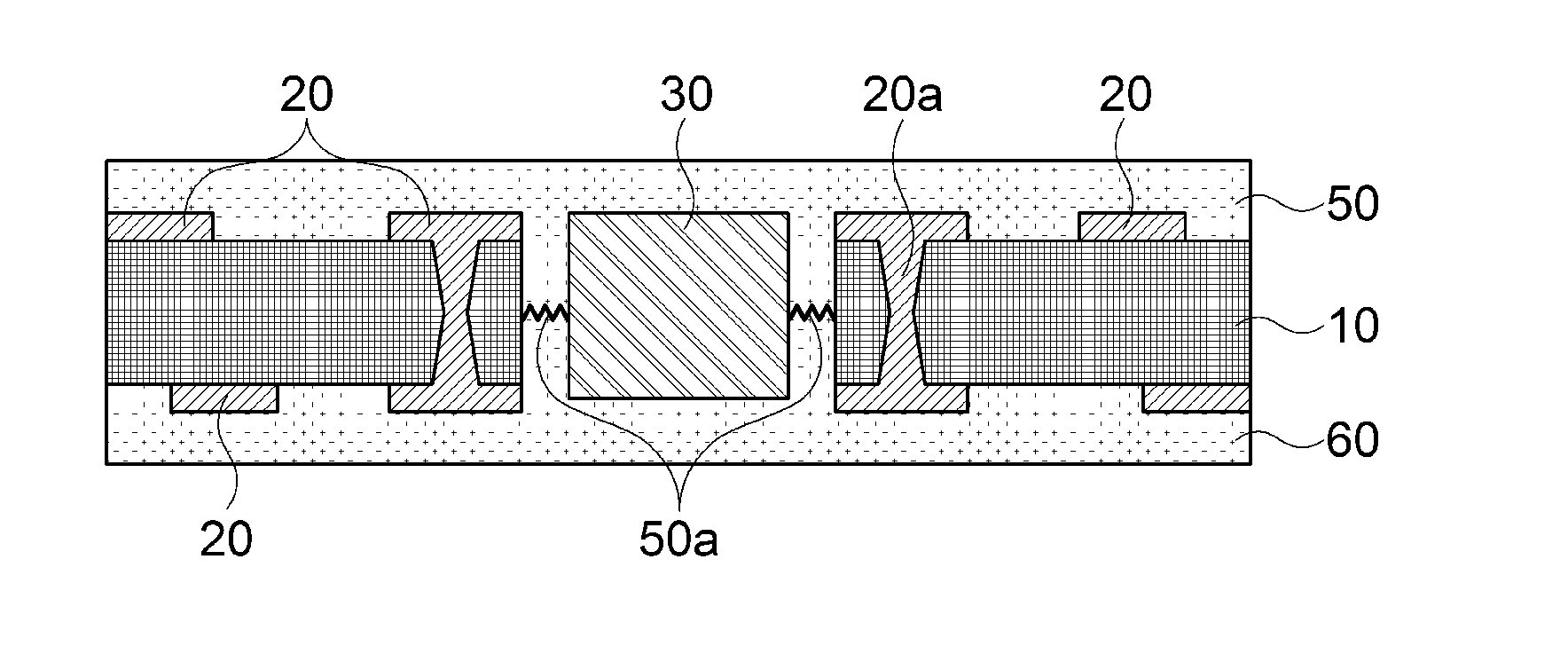
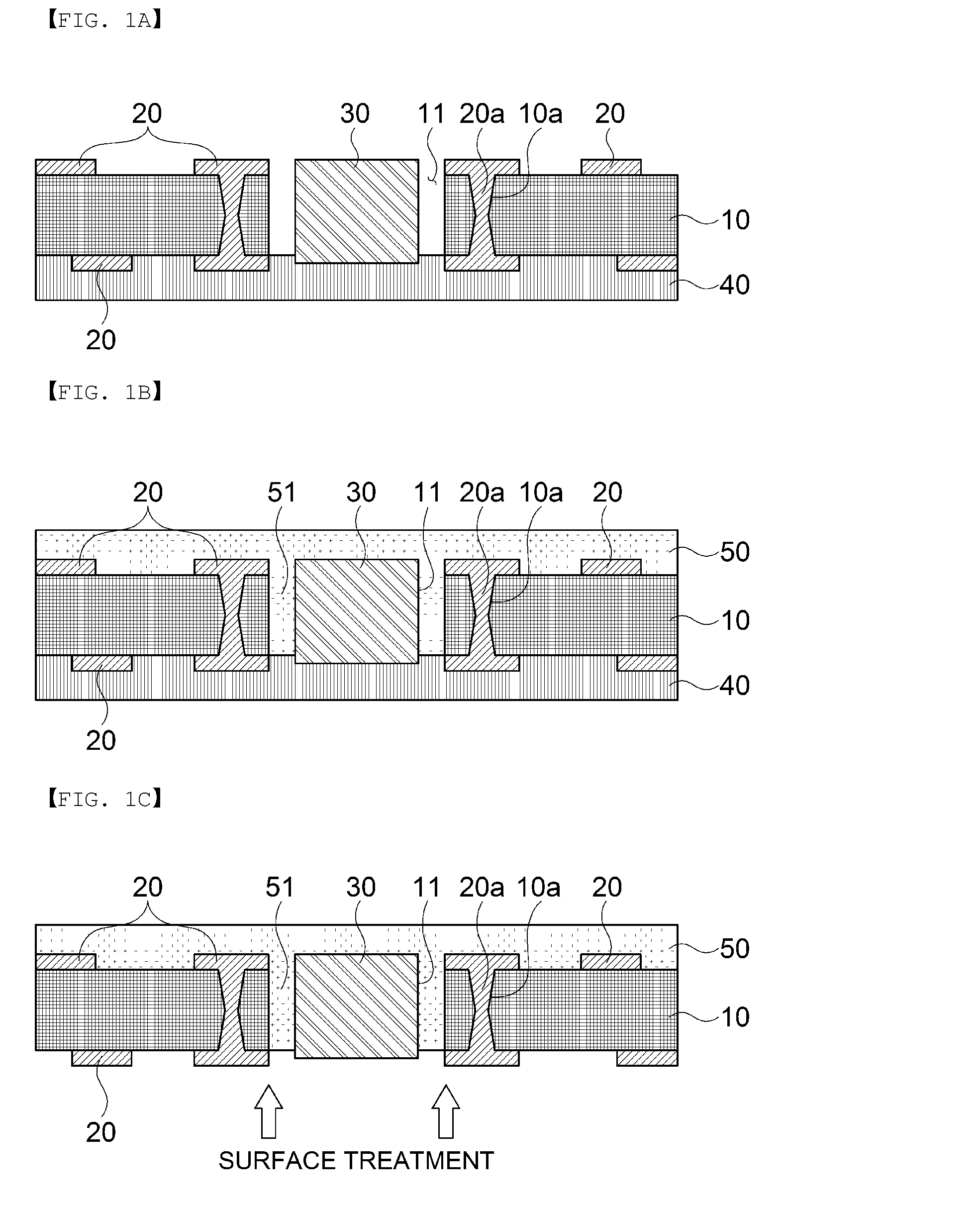
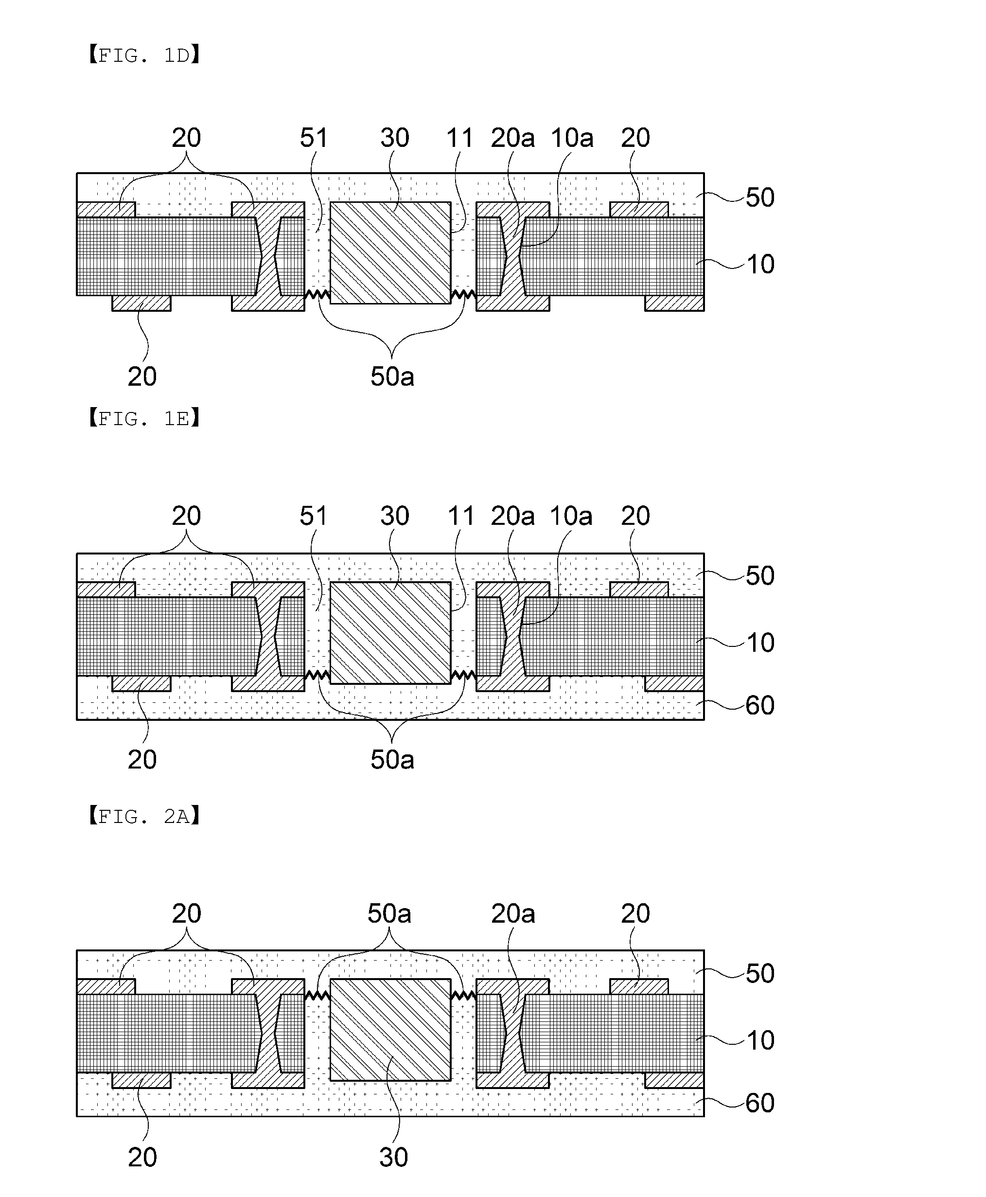
Method for manufacturing electronic component embedding substrate and electronic component embedding substrate
a technology of electronic components and embedding substrates, which is applied in the direction of printed circuit details, printed circuit non-printed electric components association, printed circuit manufacturing, etc., to achieve the effect of improving the bonding force on the bonding interface and improving the surface roughness
- Summary
- Abstract
- Description
- Claims
- Application Information
AI Technical Summary
Benefits of technology
Problems solved by technology
Method used
Image

Examples
Embodiment Construction
[0025]Exemplary embodiments of the present invention for accomplishing the above-mentioned objects will be described with reference to the accompanying drawings. In the description, the same reference numerals will be used to describe the same components of which a detailed description will be omitted in order to allow those skilled in the art to understand the present invention.
[0026]In the specification, it will be understood that unless a term such as ‘directly’ is not used in a connection, coupling, or disposition relationship between one component and another component, one component may be ‘directly connected to’, ‘directly coupled to’ or ‘directly disposed to’ another element or be connected to, coupled to, or disposed to another element, having the other element intervening therebetween.
[0027]Although a singular form is used in the present description, it may include a plural form as long as it is opposite to the concept of the present invention and is not contradictory in v...
PUM
| Property | Measurement | Unit |
|---|---|---|
| insulating | aaaaa | aaaaa |
| interface roughness | aaaaa | aaaaa |
| bonding force | aaaaa | aaaaa |
Abstract
Description
Claims
Application Information