Method for processing material to be rolled on a rolling line, and rolling line

a technology of rolling line and rolling line, which is applied in the direction of rolling speed control device, tension/compression control device, etc., can solve the problems of wire or loop breakage, tension or compression load, and the approach of very time-consuming and costly

Active Publication Date: 2016-07-28
PRIMETALS TECH GERMANY
View PDF2 Cites 1 Cited by
  • Summary
  • Abstract
  • Description
  • Claims
  • Application Information

AI Technical Summary

Benefits of technology

This patent describes a method for controlling the rotational speeds of drives in a rolling section, where multiple roll stands are used. The method uses a supplementary value to anticipatorily control the rotational speeds of all the roll stands, ensuring balanced running of all the drives. The supplementary value is fed to the rotational speed regulator of each drive in the rolling section to prevent a drop in speed at the first roll stand and maintain synchronization between the roll stands. This approach prevents loop formation and breakage of the wire between the roll stands. Overall, the method ensures a smooth and synchronized rolling process.

Problems solved by technology

Even small deviations can lead to a breakage of the wire or to loop formation.
However, a major disadvantage of this is that, for example, if there is wear in the individual rolling rings, it is always necessary to exchange or to regrind all the rolling rings, because the cross-sections or diameters of the bores must be matched to one another in order to achieve a desired result from the rolling.
This makes such an approach very time-consuming and costly.
However, a major challenge of such a drive solution is presented by the regulation of the rotational speed of the individual roll stands during the processing of goods which are being rolled.
This can lead to tension or compression loads, and hence a breakage of the wire, or to the material being rolled forming loops between the individual roll stands.
However, in particular if loop formation between the intermediate and finishing sections must not be permitted to occur, i.e. if the rotational speeds of the stands in the finishing section must also remain constant relative to the rotational speed of the last stand in the intermediate section, the method cited above is not adequate.

Method used


Image

  • Method for processing material to be rolled on a rolling line, and rolling line
  • Method for processing material to be rolled on a rolling line, and rolling line
  • Method for processing material to be rolled on a rolling line, and rolling line

Examples


Embodiment Construction

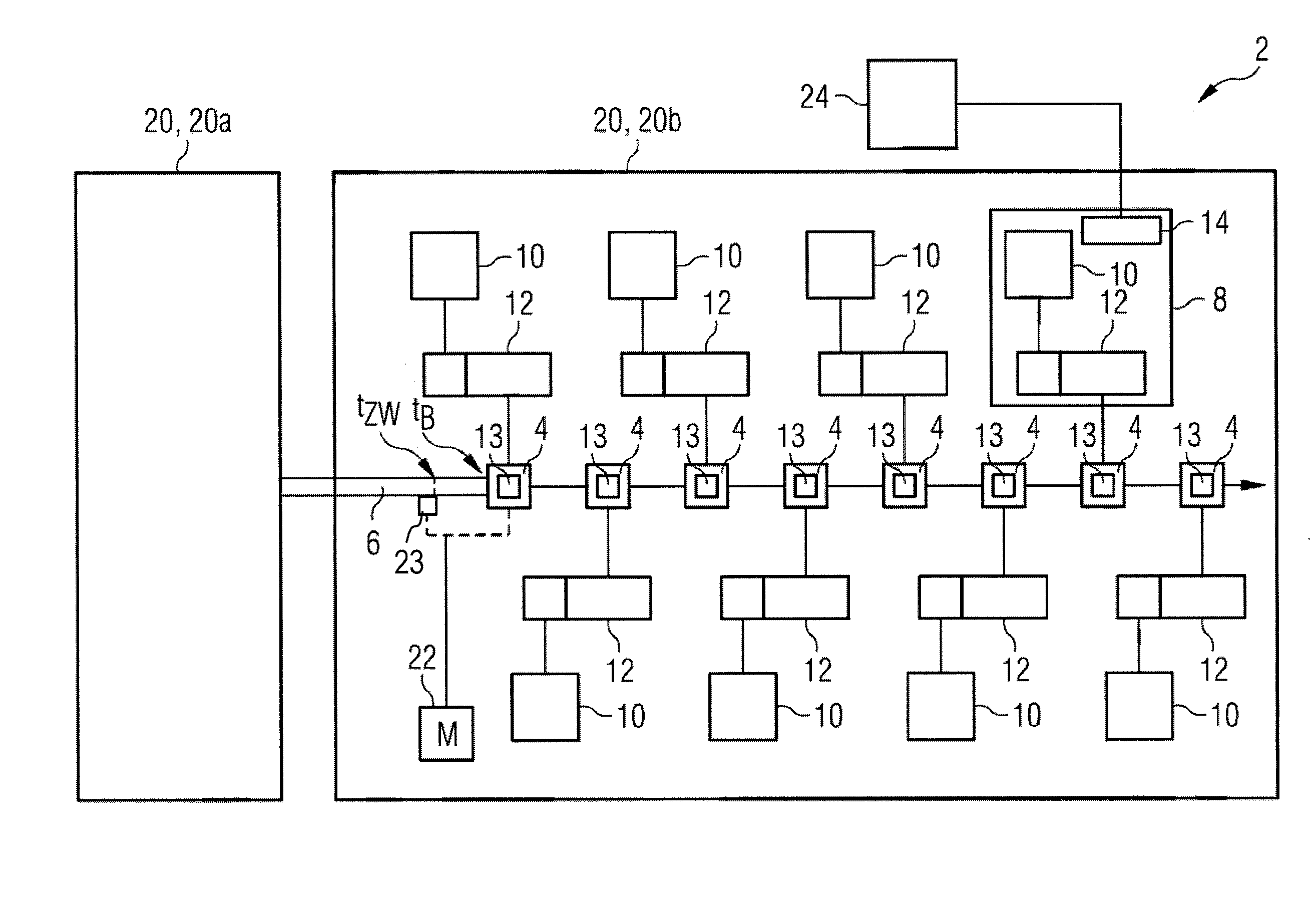
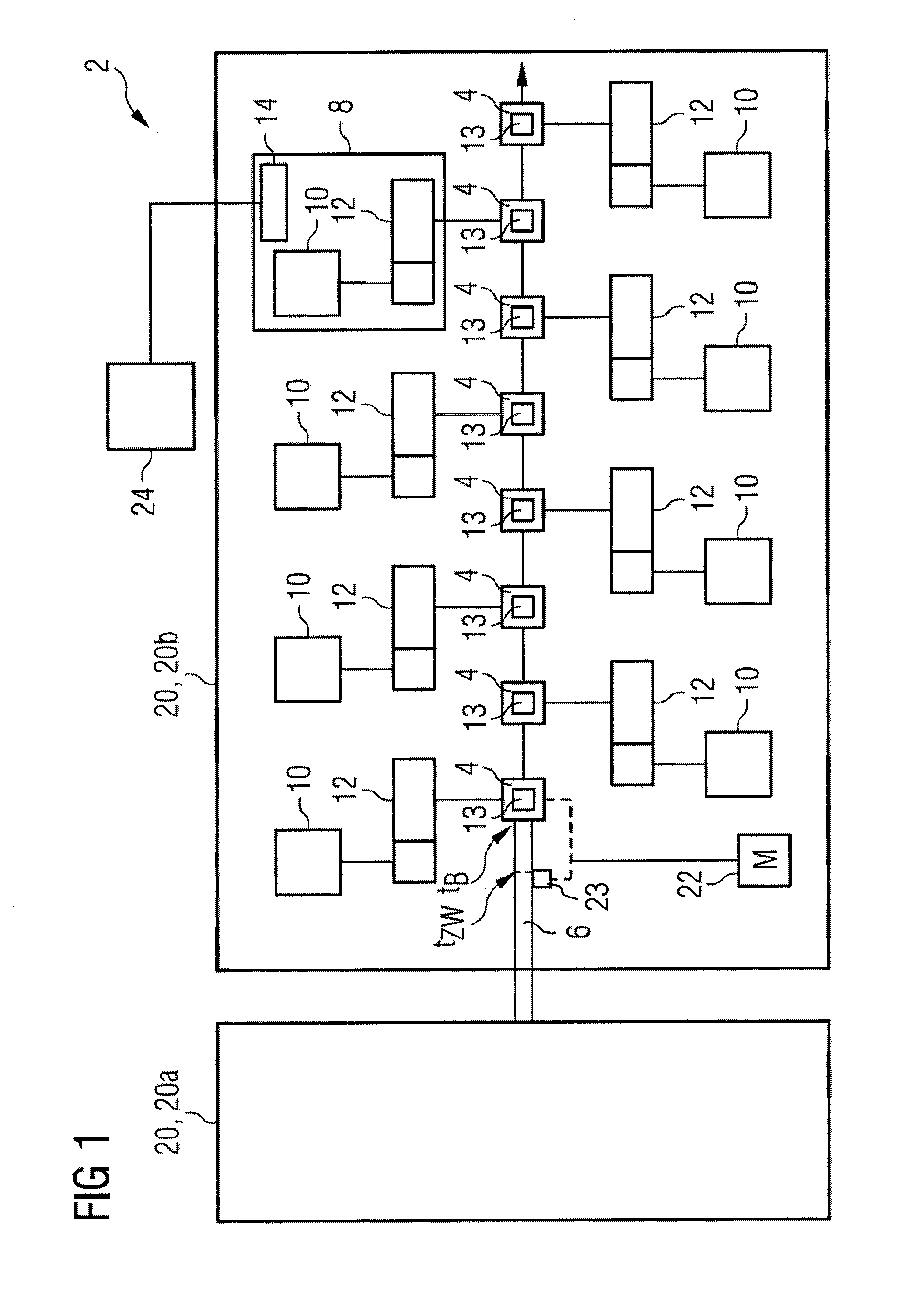
[0031]FIG. 1 shows a section of a rolling line 2 with two rolling sections 20, e.g. an intermediate section 20a and a finishing section 20b. A rolling section 20 incorporates at least two roll stands 4 each with at least one roll 13, e.g. two rolls 13, for the processing of a material to be rolled 6. FIG. 1 shows, by way of example, eight successive roll stands 4, for the sake of clarity only illustrating those for the finishing block 20b, of a rolling section 20 through which passes the material to be rolled 6, e.g. a billet which is being rolled down to wire.

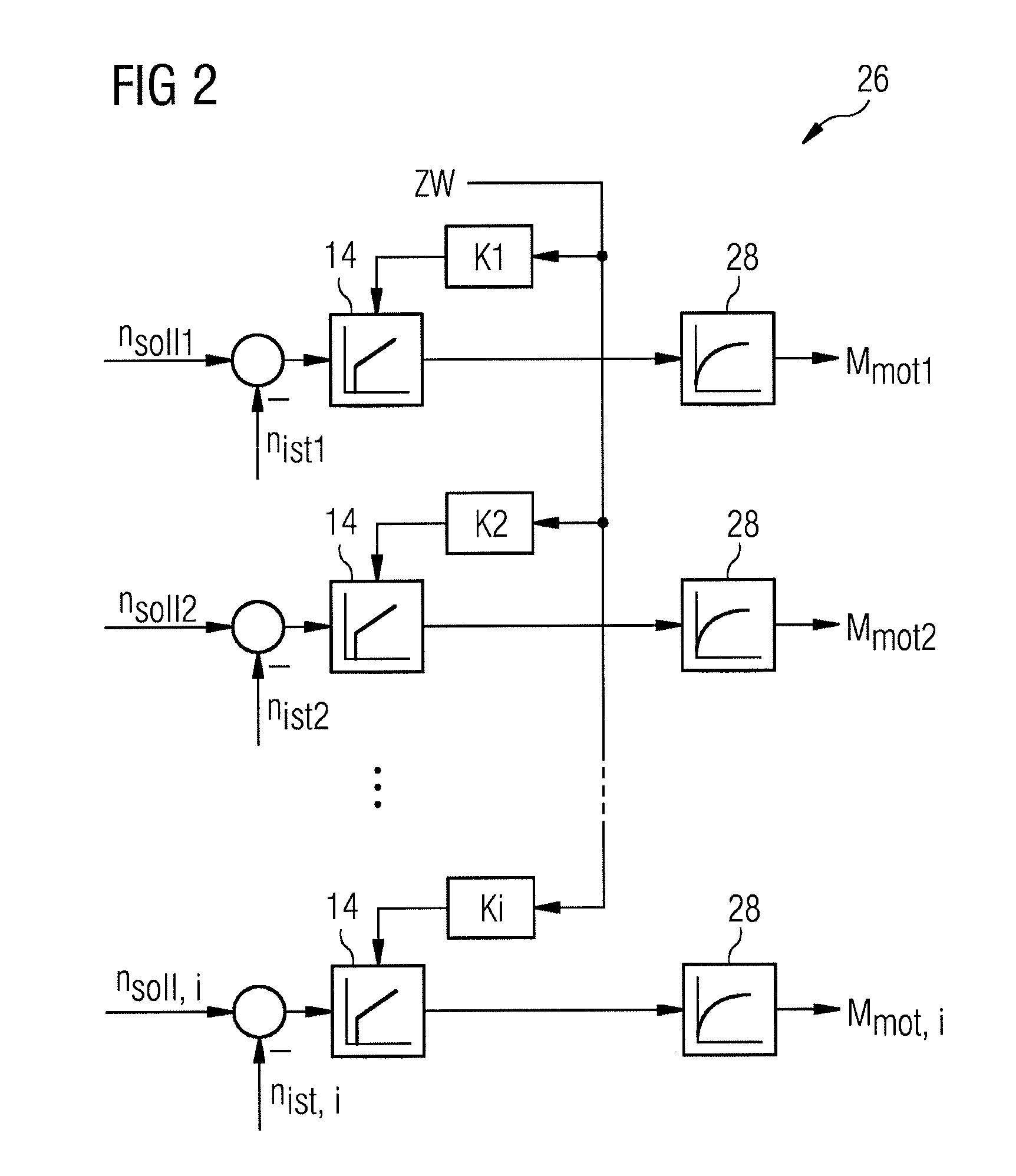
[0032]Assigned to each roll stand 4 is a separate drive 8, incorporating a motor 10 and a gearbox 12, with a rotational speed regulator 14 which, for the sake of clarity, in FIG. 1 is only drawn in for one roll stand 4. The rotational speed regulator 14 regulates the rolls 13 of the drive 8 concerned to a setpoint value, nSoll, for the rotational speed. For this purpose, an actual value of the rotational speed, nIst, is contin...


PUM

PropertyMeasurementUnit
Timeaaaaaaaaaa
Forceaaaaaaaaaa
Speedaaaaaaaaaa

Abstract

A method for machining rolled stock (6) in a rolling train (2), the train including at least one rolling block (20, 20a, 20b) having at least two rolling stands (4) with each stand including at least one roll (13). Each rolling stand (4) has a separate drive (8) with a speed controller (14) for its roll (13). A time (tZW) that is dependent on the point in time (tB) that an actual loading moment is applied to the drive (8) of the first rolling stand (4) of the rolling block (20, 20a, 20b), for controlling the speed of the drive (8). An additional value (ZW), dependent on an expected actual loading moment, is fed to the speed controller (14) of each drive (8). Also, a rolling train (2) for machining rolled stock (6), is disclosed having the features above and having an open-loop / closed-loop control unit (24), in which software for the method is implemented.

Description

CROSS-REFERENCE TO RELATED APPLICATIONS[0001]The present application is a 35 U.S.C. §§371 national phase conversion of PCT / EP2014 / 067669, filed Aug. 19, 2014, which claims priority of European Patent Application No. 13181568.0, filed Aug. 23, 2013, the contents of which are incorporated by reference herein. The PCT International Application was published in the German language.[0002]The invention relates to a method for the processing of material, particularly steel or another metal to be rolled on a rolling line with at least two roll stands each having at least one roll. A separate drive is assigned to each roll stand for its at least one roll, and a rolling line.TECHNICAL BACKGROUND[0003]In the processing of rolled materials, e.g. steel or various metals, which are in the form of so-called slabs or billets, the material being rolled passes along a rolling line with several rolling sections. The sections for example include a roughing, an intermediate and a finishing section. In t...

Claims


Application Information

Patent Timeline
IPC IPC(8): B21B37/46
CPCB21B37/46B21B37/52
Inventor WEISSHAAR, BERNHARD
Owner PRIMETALS TECH GERMANY
Why Eureka
Try Eureka