Apparatus and method to mount steering actuator

a technology of actuators and actuators, applied in the field of vehicle engineering, can solve problems such as rolling parts that interfere with normal vehicle steering

Active Publication Date: 2016-07-28
AGJUNCTION
View PDF6 Cites 34 Cited by
  • Summary
  • Abstract
  • Description
  • Claims
  • Application Information

AI Technical Summary

Benefits of technology

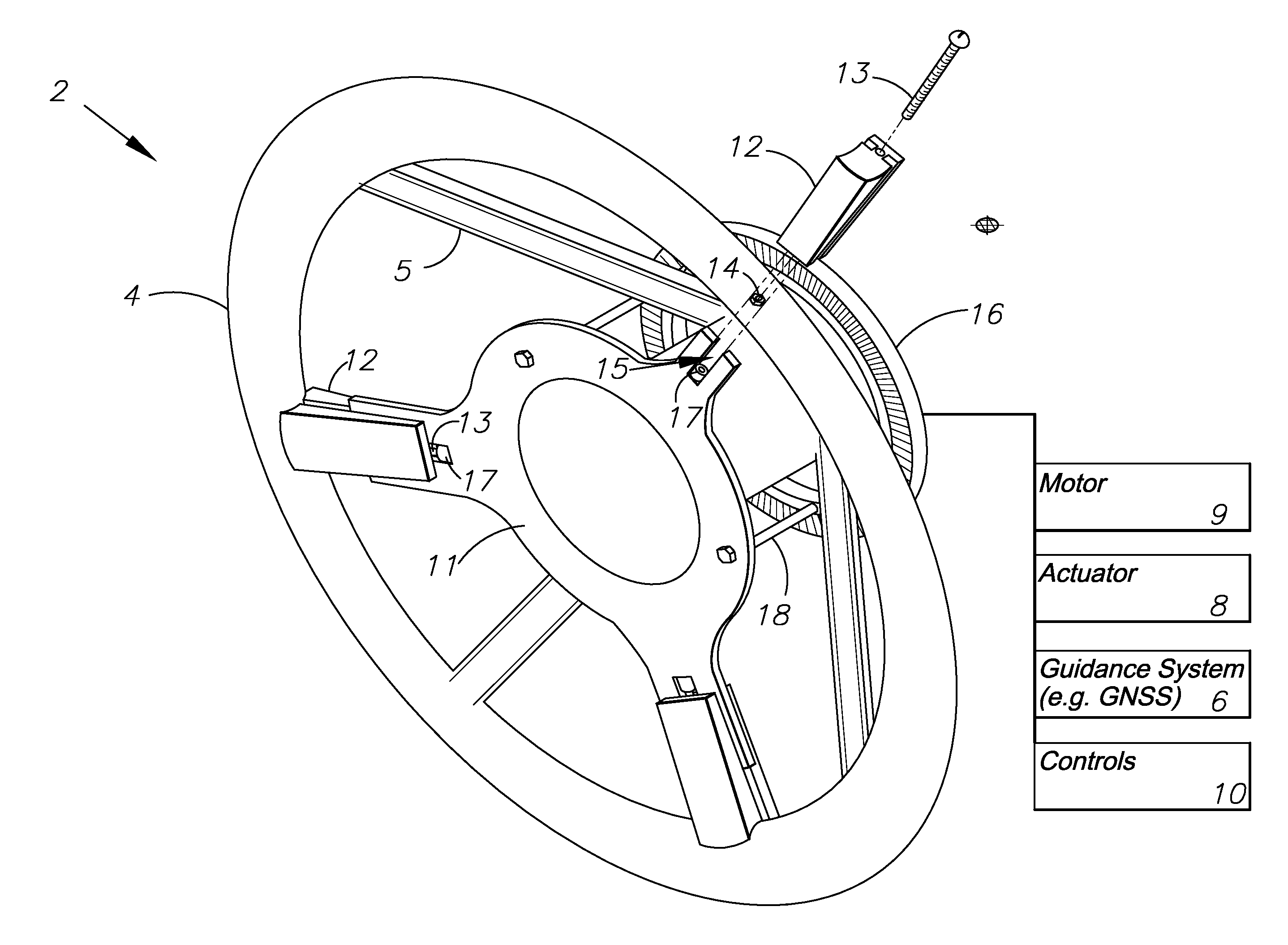
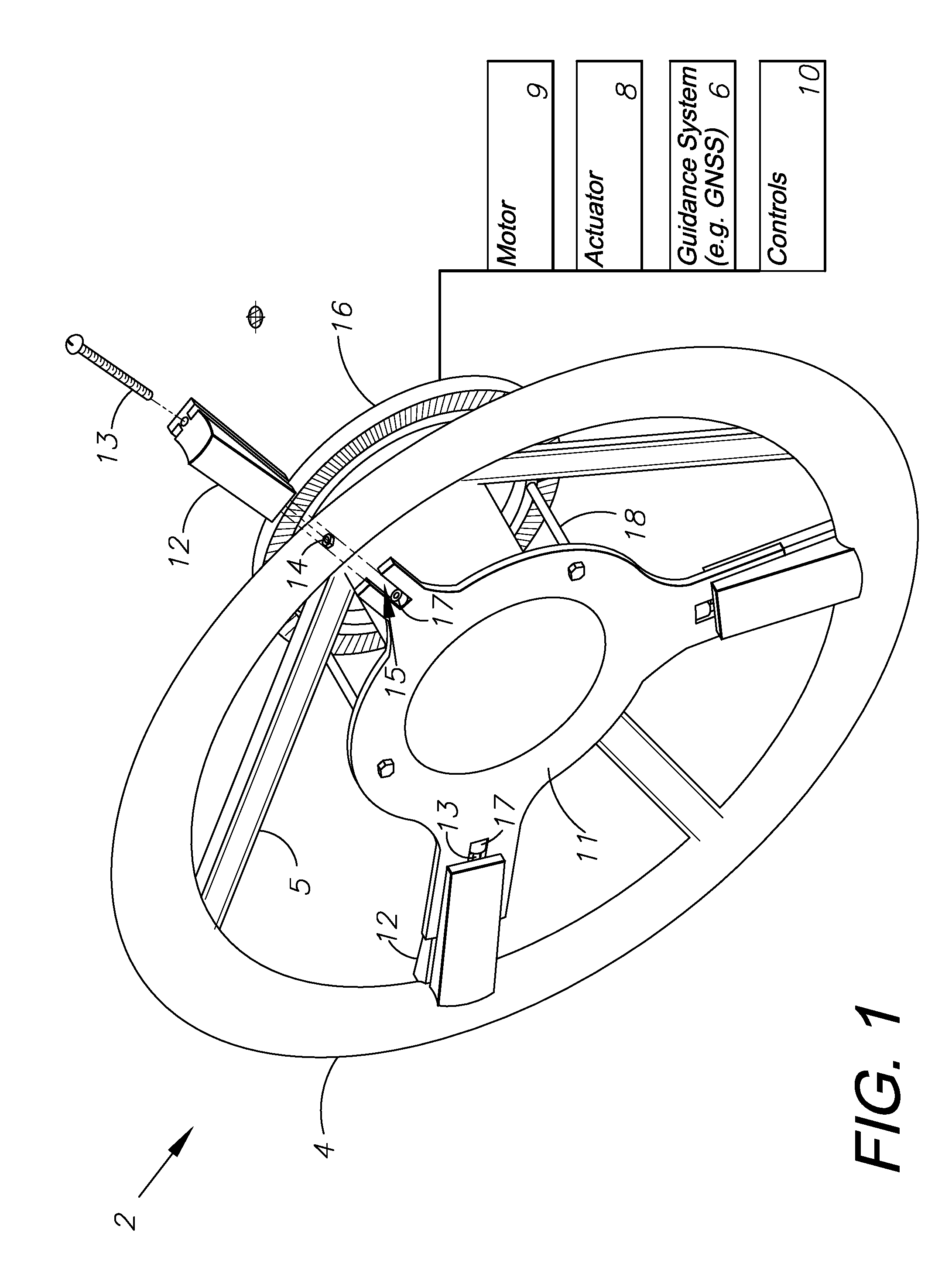
[0011]The present invention is an apparatus and method for installing electrical, mechanical or other steering actuators above or below the factory steering wheel on vehicles, without having to remove the steering wheel while fitting even on steering wheels with two or fewer spokes and steering wheels with uneven spoke spacing.
[0013]The adjustment mechanism of the invention allows the precise centering of the steering actuator so that it is aligned with the steering shaft.
[0014]The adjustment mechanism of the invention and the three points of contact with the steering wheel rim allow the invention to be retained securely through friction inside the steering wheel. The secure retention allows the transmission of torque from a steering wheel actuator to the steering wheel for purposes of steering the vehicle.
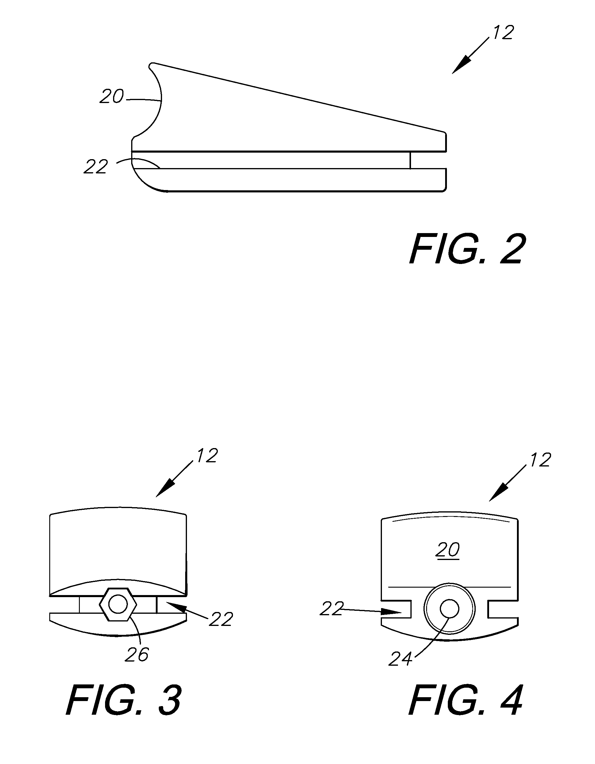
[0018]The invention has adjustable sliders of a novel design that simplify the assembly and reduce the number of parts. The invention as shown only has two distinct parts; the center plate and the slider elements, and the total number of nonstandard hardware parts is only four (one center plate and three sliders). The low part count leads to simplicity and low cost.

Problems solved by technology

Although very simple, the roller can interfere with normal vehicle steering since it is an obstacle for the driver's hand.
All the previously mentioned steering actuators significantly interfere with the factory steering wheel, or require the factory steering wheel to be removed for installation.

Method used


Image

  • Apparatus and method to mount steering actuator
  • Apparatus and method to mount steering actuator
  • Apparatus and method to mount steering actuator

Examples


Embodiment Construction

I. Introduction and Environment

[0028]As required, detailed aspects of the present invention are disclosed herein, however, it is to be understood that the disclosed aspects are merely exemplary of the invention, which may be embodied in various forms. Therefore, specific structural and functional details disclosed herein are not to be interpreted as limiting, but merely as a basis for the claims and as a representative basis for teaching one skilled in the art how to variously employ the present invention in virtually any appropriately detailed structure.

[0029]Certain terminology will be used in the following description for convenience in reference only and will not be limiting. For example, up, down, front, back, right and left refer to the invention as orientated in the view being referred to. The words, “inwardly” and “outwardly” refer to directions toward and away from, respectively, the geometric center of the aspect being described and designated parts thereof. Forwardly and ...


PUM


Abstract

A steering actuator system to be mounted to the steering wheel and steering column of a vehicle. The steering actuator system includes a flat baseplate with multiple adjustable sliders. These sliders slide along channel guides within the flat baseplate to accommodate steering wheels of varying sizes. The system includes a gear which mounts below the steering wheel, possibly around the steering column of the vehicle. A steering actuator powered by a motor or some other power source is connected to the gear and when activated can actively steer the vehicle. When connected to a guidance system, the vehicle can automatically be guided and steered via the guidance system and the steering actuator system. This provides a convenient way to add automatic steering to any vehicle with a steering wheel.

Description

CROSS-REFERENCE TO RELATED APPLICATION[0001]This application claims priority in U.S. Provisional Patent Application No. 62 / 108,186, filed Jan. 27, 2015, which is incorporated herein by reference.BACKGROUND OF THE INVENTION[0002]1. Field of the Invention[0003]The present invention is in the technical field of vehicle engineering. More particularly, the present invention is in the technical field of Global Navigation Satellite System (GNSS) auto-steering applications.[0004]2. Description of the Related Art[0005]Several electric actuators have been developed for automatically turning the steering wheel of vehicles. These systems use electric motors and drive mechanisms to turn the steering wheel through friction wheels, gears, belt drives and direct drive motors installed under the steering wheel.[0006]A prior-art method is disclosed in a product called EZ-Steer launched by Trimble Navigation Ltd. Of Sunnyvale, Calif. in 2004 that uses an electric motor with a soft friction wheel to tu...

Claims


Application Information

Patent Timeline
Patent Type & Authority Applications(United States)
IPC IPC(8): B62D6/00G01S19/42B62D5/04B62D1/08
CPCB62D6/00B62D5/0409G01S19/42B62D1/08B62D1/00B62D5/04G01S19/14G05D1/0278G05D2201/0213
Inventor JOUGHIN, ALAN ROBERT
Owner AGJUNCTION
Why Eureka
Try Eureka