Gas turbine laminate seal assembly comprising first and second honeycomb layer and a perforated intermediate seal plate in-between

a technology of laminate seals and honeycombs, which is applied in the manufacture of engines, climate sustainability, sustainable transportation, etc., can solve the problems of exhaust gas temperature overshoot, open between sealing features, and reduce the functionality of seals, so as to reduce gaps and minimize the growth of stators and rotors.

Inactive Publication Date: 2016-07-28
GENERAL ELECTRIC CO
View PDF10 Cites 21 Cited by
  • Summary
  • Abstract
  • Description
  • Claims
  • Application Information

AI Technical Summary

Benefits of technology

[0009]According to present embodiments, a seal assembly is provided which thermally matches the stator and rotor growths so that differential growth between the stator and rotor is minimized. The growth of the stator portion of the seal is tuned to more closely approximate the slower growth of the ro

Problems solved by technology

Such growth differential results in opening between the sealing features and reduced functionality of the seal.
As a result, gaps between the stator portion and the

Method used


Image

  • Gas turbine laminate seal assembly comprising first and second honeycomb layer and a perforated intermediate seal plate in-between
  • Gas turbine laminate seal assembly comprising first and second honeycomb layer and a perforated intermediate seal plate in-between
  • Gas turbine laminate seal assembly comprising first and second honeycomb layer and a perforated intermediate seal plate in-between

Examples


first embodiment

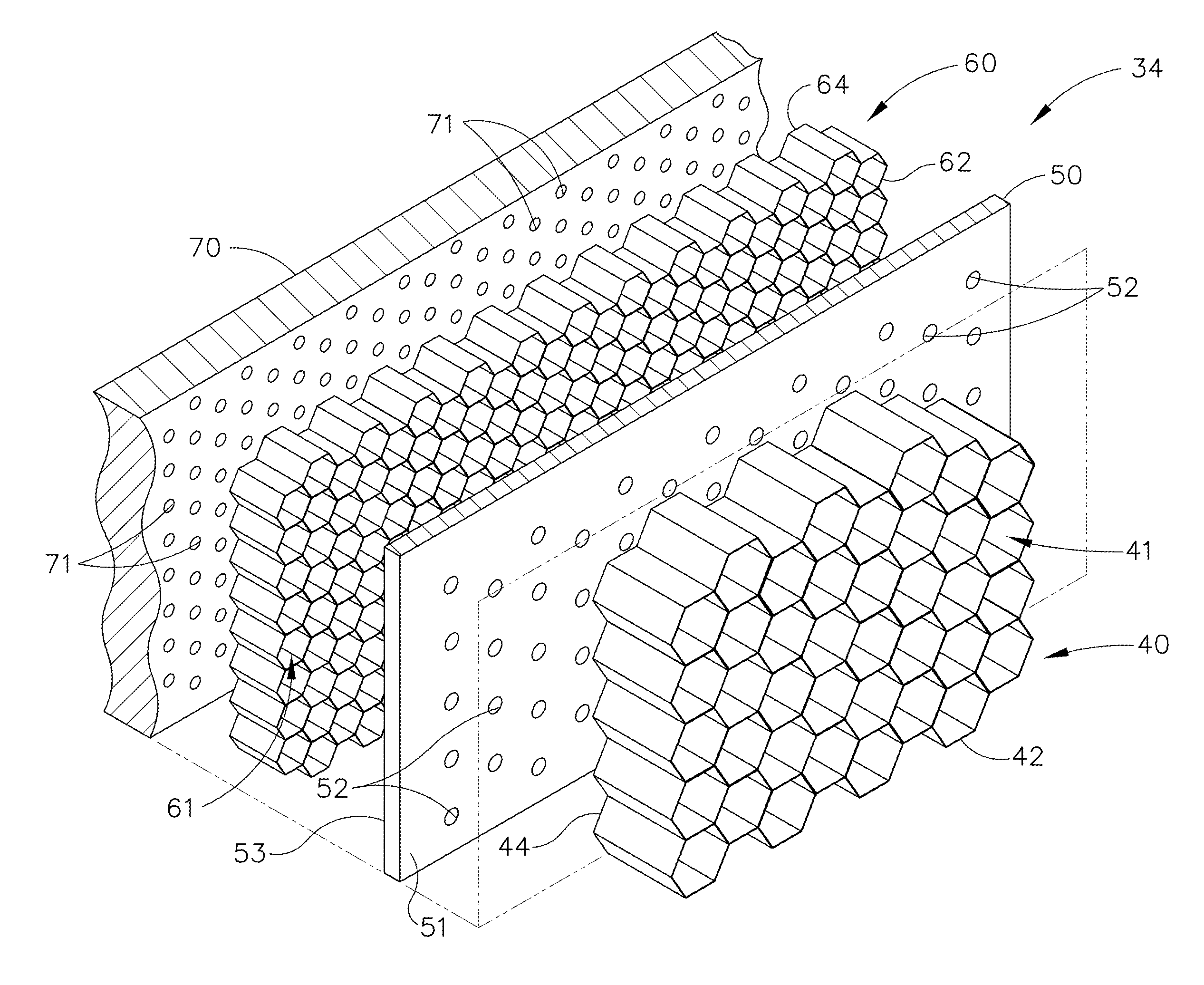
[0035]Referring now to FIG. 3, an exploded assembly of the laminate seal assembly 34 is depicted. The laminate seal assembly 34 is formed of a laminate of materials and comprises a radially inward first honeycomb layer 40 which is closest to the seal teeth 32 (FIG. 2) during operation of the engine. The first honeycomb layer 40 includes a plurality of honeycomb cells 41 defined by thin walls. The first honeycomb layer 40 is made of a plurality of honeycomb cells 41 which are generally hollow and extend between a first edge 42 and a second edge 44. Although the term “honeycomb” is utilized herein, the term should not be considered to be limiting of the geometric shape of the honeycomb cells 41. While six-sided cells are shown, the various shapes may be utilized including circular, square, rectangular or other geometric shapes. The honeycomb cells 41 each have a height extending from a first edge 42 to a second edge 44 of the first honeycomb layer 40. The first honeycomb layer 40 mate...

second embodiment

[0041]Referring now to FIG. 5, an exploded assembly view of the double layer laminate seal assembly 134 is depicted. The thermal laminate structure includes a first radially inward honeycomb layer 140 which may be of similar description to the first honeycomb layer 40 previously described. For example, the first honeycomb layer 140 includes an inner edge 142 and an outer edge 144. Positioned on the radially outer edge 144 of the first honeycomb layer 140 is an intermediate seal plate 150 which may be a low conductivity material positioned between the first honeycomb layer 140 and a low conductivity structure 160. The intermediate seal plate 150 may or may not be bonded to the low conductivity structure 160. The intermediate seal plate 150 may include a plurality of apertures or may be solid as depicted. In the instance that perforations are utilized, they may vary in size, shape, number and arrangement as previously described.

[0042]Above or radially outward from the intermediate sea...


PUM


Abstract

A laminate seal assembly, disposed on a stator seal portion and opposite a rotor seal portion of a gas turbine engine comprises a first honeycomb layer having a first edge which engages the rotor portion and a second edge distal from said rotor seal portion, a plurality of honeycomb cells extending between the first edge and the second edge, an intermediate seal plate having a first material surface and a second material surface, the first material surface disposed against the second edge of the first honeycomb layer, a low conductivity structure disposed on the second surface, and a backing plate disposed on against said low conductivity structure, wherein the stator portion may be tuned for thermal growth to match the thermal growth of the rotor portion.

Description

CROSS-REFERENCE TO RELATED APPLICATIONS[0001]This application is a national stage application under 35 U.S.C. §371(c) of prior filed, co-pending PCT application serial number PCT / US2014 / 050797, filed on Aug. 13, 2014, which claims priority to U.S. patent application Ser. No. 61 / 874,608, titled “Double Layer Lattice on Labyrinth Seals for Thermal Matching and Method”, filed Sep. 6, 2013.The above-listed applications are herein incorporated by reference.BACKGROUND[0002]Present embodiments relate generally to gas turbine engines. More particularly, but not by way of limitation, present embodiments relate to a laminate lattice structure for thermal matching of seal components and associated methods.[0003]A typical gas turbine engine generally possesses a forward end and an aft end with its several core or propulsion components positioned axially therebetween. An air inlet or intake is at a forward end of the gas turbine engine. Moving toward the aft end, in order, the intake is followed...

Claims


Application Information

Patent Timeline
IPC IPC(8): F01D11/18
CPCF01D11/18F05D2220/32F05D2230/237F05D2250/283F05D2240/20F05D2240/10F05D2230/50F01D11/025F01D11/12Y02T50/60
Inventor GONYOU, CRAIG ALANUPDIKE, GREGORY ALLEN
Owner GENERAL ELECTRIC CO
Why Eureka
Try Eureka