Eureka AIR delivers breakthrough ideas for toughest innovation challenges, trusted by R&D personnel around the world.

Flow restrictor assemblies including a monolithic flow restrictor and methods for manufacturing the same

Active Publication Date: 2016-07-28
HONEYWELL INT INC
View PDF1 Cites 5 Cited by
  • Summary
  • Abstract
  • Description
  • Claims
  • Application Information

AI Technical Summary

Benefits of technology

The present invention provides a flow restrictor assembly for use in hydraulic assemblies or other applications. The flow restrictor is made of a single piece of material that is placed in a housing body. It includes a screen and a series of cross-sectional portions with slots and restricting orifices that allow fluid to flow through the assembly in a tortuous manner. The assembly also includes a close tolerance with the housing body to seal the slots. The flow restrictor is manufactured using additive manufacturing and machining. The technical effects of the invention include improved flow control, increased efficiency, and reduced pressure drop.

Problems solved by technology

Unfortunately, even after hydraulic systems are cleaned and filtered, there may be metal or dirt particulate in the hydraulic system that can clog an orifice of the flow restrictor, causing the hydraulic system to fail.
However, a conventional multi-stage flow restrictor requires precise machining in order to effect the desired flow restriction, making it expensive and difficult to manufacture.
As a result, a conventional multi-stage flow restrictor represents a significant cost in the hydraulic system in which it is used.
Furthermore, maintaining different sizes of conventional multi-stage flow restrictors on hand is necessary for compatibility with different fittings therefor, further increasing costs.

Method used


Image

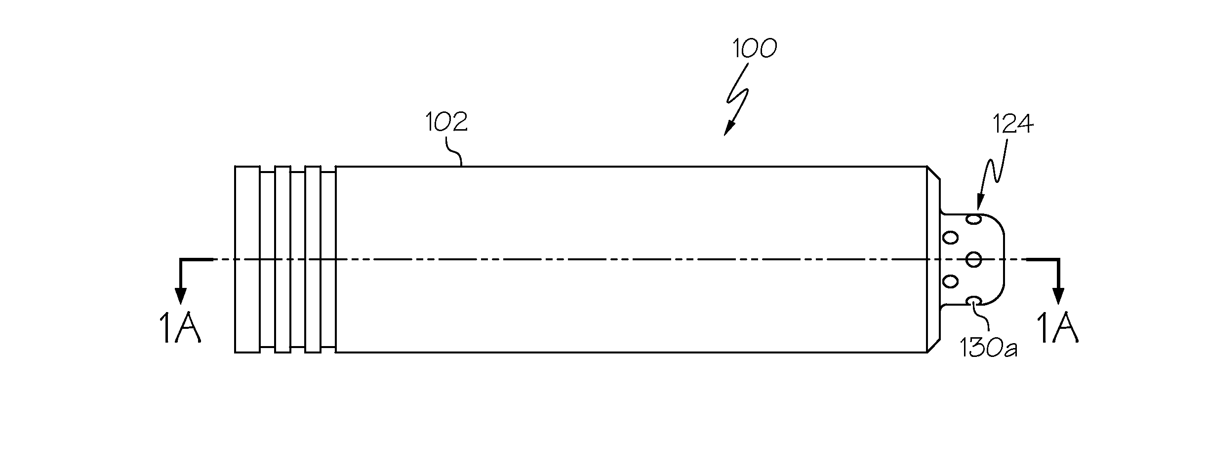
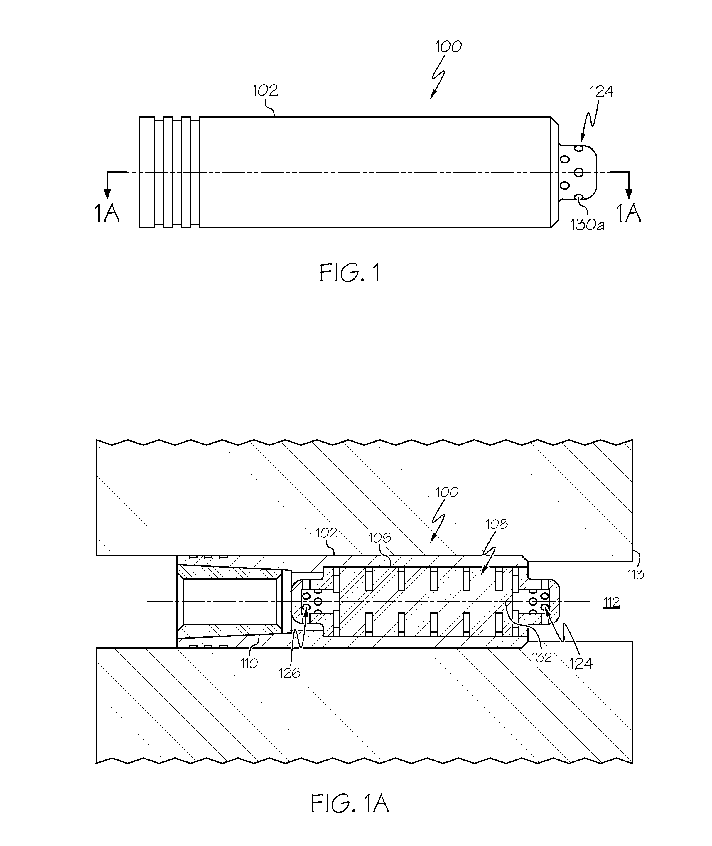
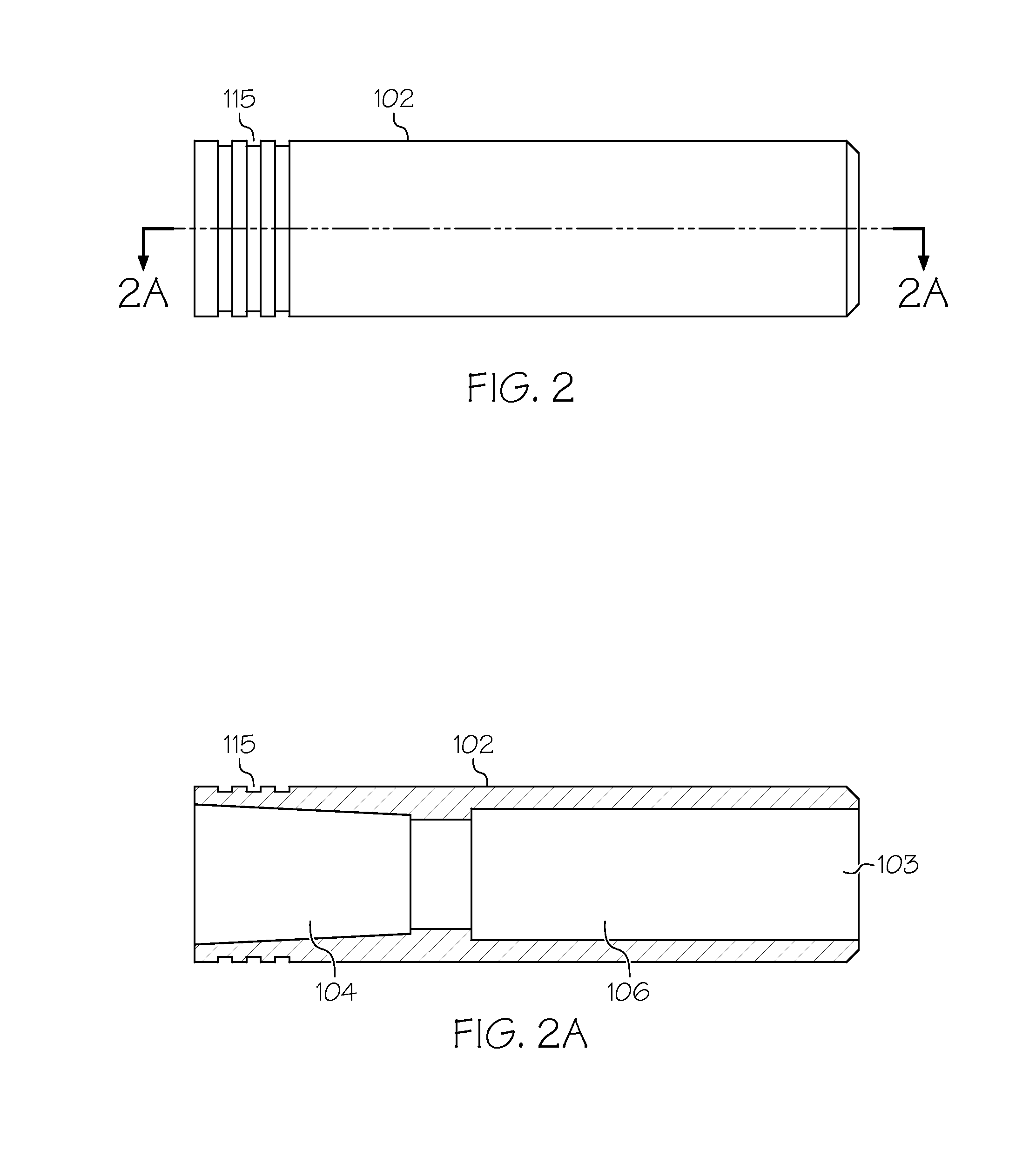
  • Flow restrictor assemblies including a monolithic flow restrictor and methods for manufacturing the same
  • Flow restrictor assemblies including a monolithic flow restrictor and methods for manufacturing the same
  • Flow restrictor assemblies including a monolithic flow restrictor and methods for manufacturing the same

Examples


Embodiment Construction

[0026]The following detailed description is merely exemplary in nature and is not intended to limit the invention or the application and uses of the invention. As used herein, the word “exemplary” means “serving as an example, instance, or illustration.” Thus, any embodiment described herein as “exemplary” is not necessarily to be construed as preferred or advantageous over other embodiments. All of the embodiments described herein are exemplary embodiments provided to enable persons skilled in the art to make or use the invention and not to limit the scope of the invention which is defined by the claims. Furthermore, there is no intention to be bound by any expressed or implied theory presented in the preceding technical field, background, brief summary, or the following detailed description.

[0027]Various embodiments are directed to flow restrictor assemblies including a monolithic flow restrictor and methods for manufacturing the same. The flow restrictor assembly may be used in a...


PUM

PropertyMeasurementUnit
Particle sizeaaaaaaaaaa
Flow rateaaaaaaaaaa

Abstract

Flow restrictor assemblies including a monolithic flow restrictor and methods for manufacturing the same are provided. The monolithic flow restrictor is configured for disposing in a fluid passage of a housing body. The monolithic flow restrictor comprises a first end and a second end, a first screen at the first end and a second screen at the second end, and a series of cross-sectional portions between the first screen and the second screen. Each cross-sectional portion has a plurality of slots formed in a radially outer surface thereof for connecting a series of restricting orifices formed in the monolithic flow restrictor for tortuously conducting a fluid through the series of cross-sectional portions.

Description

TECHNICAL FIELD[0001]The present invention generally relates to gas turbine engines, and more particularly relates to flow restrictor assemblies including a monolithic flow restrictor and methods for manufacturing the same.BACKGROUND[0002]Hydraulic systems such as fuel control systems use flow restrictors to control and / or balance the pressure drop and mass flow rate of a fluid flow through a fluid channel. Unfortunately, even after hydraulic systems are cleaned and filtered, there may be metal or dirt particulate in the hydraulic system that can clog an orifice of the flow restrictor, causing the hydraulic system to fail. Single-stage flow restrictors include a single orifice. Conventional multi-stage flow restrictors include a series of stacked discrete plates with multiple larger orifices. With a multi-stage flow restrictor, the fluid and particulate are channeled through the multiple larger orifices instead of through just one orifice, reducing fluid exit velocity, pressure, and...

Claims


Application Information

Patent Timeline
IPC IPC(8): F16L55/07B22F5/10B22F3/24F16L55/24B22F3/105
CPCF16L55/07F16L55/24B22F3/1055B22F2003/247B22F5/10B33Y10/00B33Y80/00B22F3/24B22F2998/10F16L55/02736F16L55/02781Y02P10/25B22F10/28B22F10/66B22F10/68
Inventor LEWIS, STEVEN ALANSPIER, MICHAEL J.WILLIAMS, JAMESVALENCOURT, GARY A.GIBBS, ANTHONY M.
Owner HONEYWELL INT INC
Why Eureka
Eureka Blog
Learn More