
Power supply system for outboard motor, outboard motor boat, and outboard motor

a power supply system and outboard motor technology, applied in the direction of marine propulsion, propulsive elements, vessel construction, etc., can solve the problems of increasing the volume and weight of the transmission line, the difficulty of making the current larger, and the increase of the volume of the transmission line. , to achieve the effect of reducing or preventing an increase in the diameter of the transmission line and increasing the electric power of the transmission lin

Active Publication Date: 2016-07-28
YAMAHA MOTOR CO LTD
View PDF0 Cites 5 Cited by
  • Summary
  • Abstract
  • Description
  • Claims
  • Application Information

AI Technical Summary

Benefits of technology

The invention provides a system for powering outboard motors and boats that allows for more electric power transmission without increasing the size of the transmission line. This helps to improve performance and efficiency.

Problems solved by technology

In this case, it is difficult to make the current larger than a current transmittable according to the diameter of a transmission line and transmit more electric power.
Also in the charging system for a small boat according to the aforementioned Japanese Patent Laying-Open No. 2001-128388, a voltage is restricted by a battery voltage during electric power transmission, similarly to in the power supply system for the marine propulsion device described in the aforementioned U.S. Pat. No. 5,681,193, and hence it may be difficult to transmit more electric power.
If the diameter of the transmission line is increased, however, the volume and weight of the transmission line is increased.

Method used


Image

  • Power supply system for outboard motor, outboard motor boat, and outboard motor
  • Power supply system for outboard motor, outboard motor boat, and outboard motor
  • Power supply system for outboard motor, outboard motor boat, and outboard motor

Examples


first embodiment

[0042](Structure of Outboard Motor Boat)

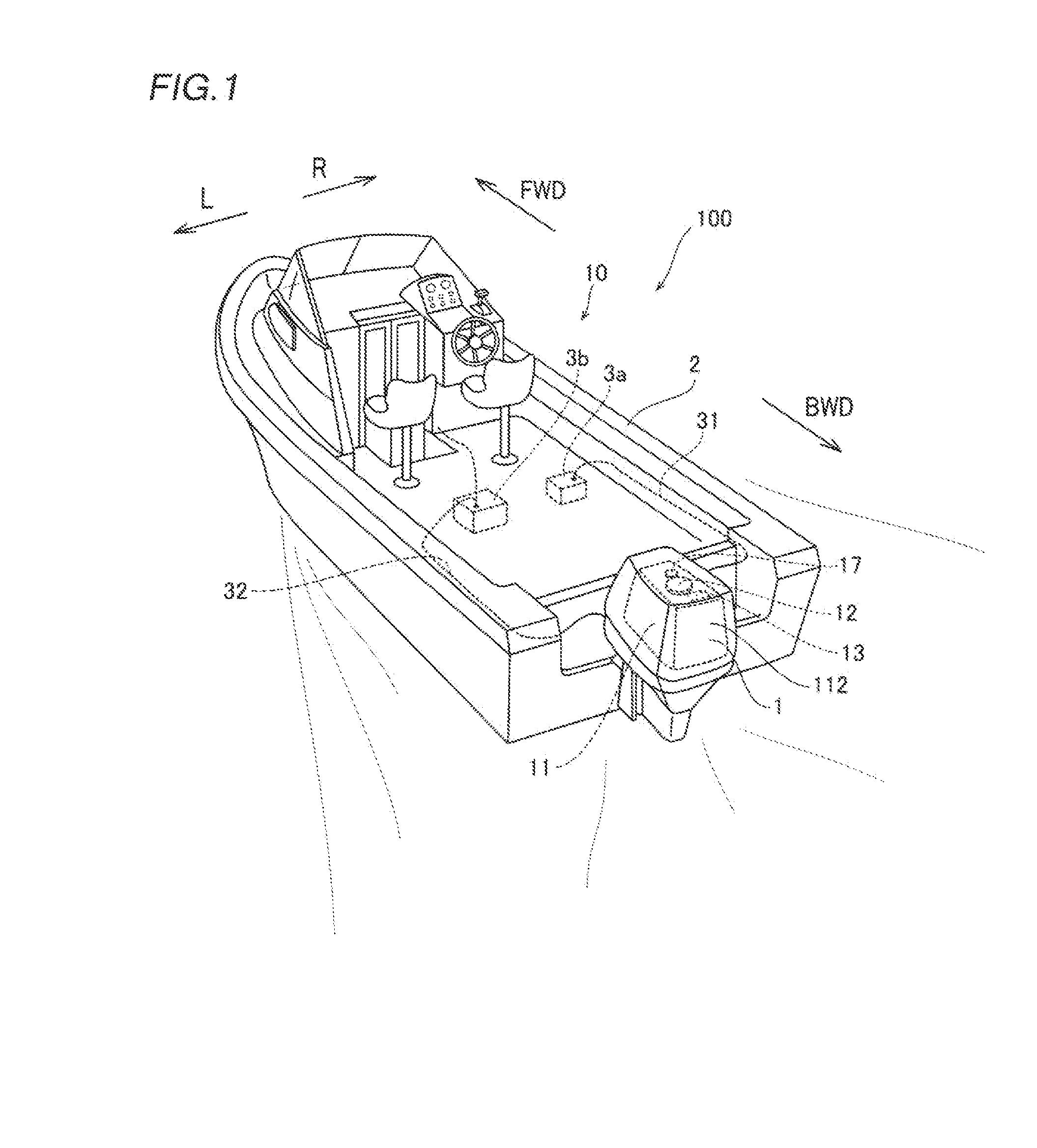
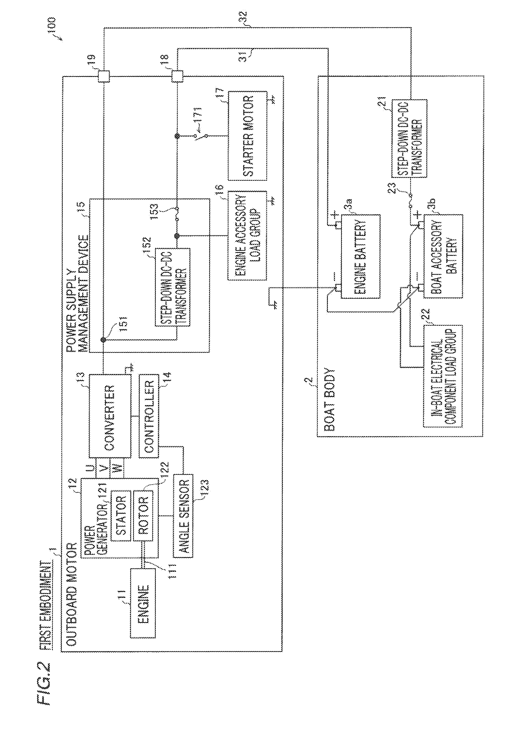
[0043]The structure of an outboard motor boat 10 according to a first embodiment of the present invention is now described with reference to FIGS. 1 and 2. In the figure, arrow FWD represents the forward movement direction of the outboard motor boat 10, and arrow BWD represents the reverse movement direction of the outboard motor boat 10. Furthermore, in the figure, arrow R represents the starboard direction of the outboard motor boat 10, and arrow L represents the portside direction of the outboard motor boat 10.

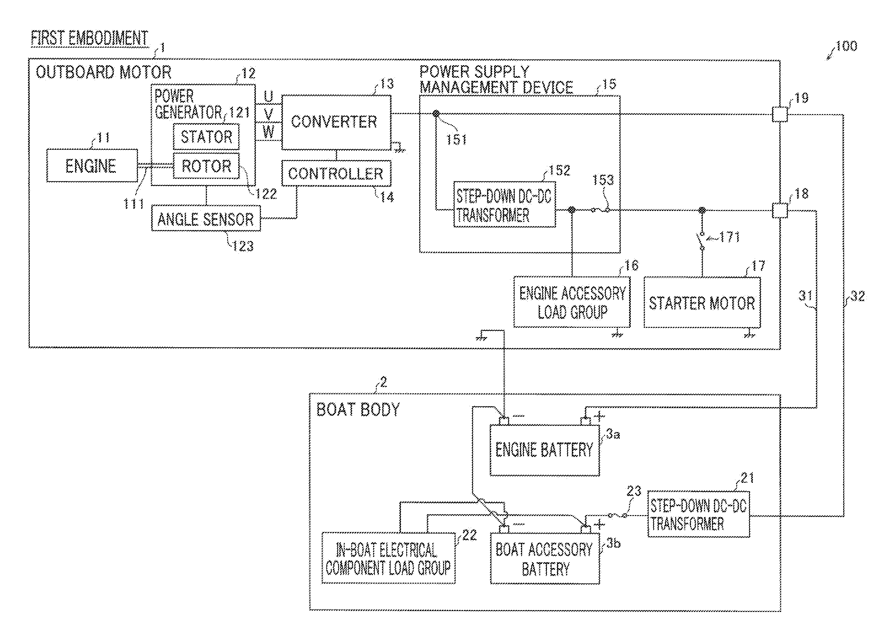
[0044]The outboard motor boat 10 includes an outboard motor 1, a boat body 2, an engine battery 3a, and a boat accessory battery 3b, as shown in FIG. 1. One outboard motor 1 is provided on a rear portion of the boat body 2. The engine battery 3a is connected to the outboard motor 1 through a cable 31. The boat accessory battery 3b is connected to the outboard motor 1 through a cable 32.

[0045]The outboard motor 1 includes an engine 11,...

second embodiment

[0076](Structure of Power Supply System for Outboard Motor)

[0077]A second embodiment of the present invention is now described with reference to FIGS. 3 and 4. In this second embodiment, the potential of a second terminal is higher than that of a branch portion, unlike the aforementioned first embodiment in which the potential of the second terminal is substantially equal to that of the branch portion. Portions similar to those of the power supply system 100 for an outboard motor according to the first embodiment are denoted by the same reference numerals.

[0078]As shown in FIG. 3, a power supply management device 201 of a power supply system 200 for an outboard motor according to the second embodiment includes a branch portion 151, a step-down DC-DC transformer 152, a fuse 153, and a step-up DC-DC transformer 154. In other words, according to the second embodiment, the step-up DC-DC transformer 154 is provided between the branch portion 151 and a second terminal 19. The step-up DC-D...


PUM


Abstract

A power supply system for an outboard motor includes a first terminal configured to supply electric power converted by a converting device to an engine accessory and to be capable of supplying the electric power to a portion external to an engine cover and a second terminal branched from a branch portion between the converting device and the engine accessory, configured to be capable of supplying the electric power to a portion external to the engine cover at a voltage higher than the voltage of the first terminal.

Description

CROSS-REFERENCE TO RELATED APPLICATION[0001]The priority application number JP2015-014048, Power Supply System for Outboard Motor, Outboard Motor Boat, and Outboard Motor, Jan. 28, 2015, Shiro Fukuda and Kazuyuki Umiguchi, upon which this patent application is based is hereby incorporated by reference.BACKGROUND OF THE INVENTION[0002]1. Field of the Invention[0003]The present invention relates to a power supply system for an outboard motor, an outboard motor boat, and an outboard motor.[0004]2. Description of the Background Art[0005]A power supply system for an outboard motor is known in general. Such a power supply system for an outboard motor is disclosed in U.S. Pat. No. 5,681,193 and Japanese Patent Laying-Open No. 2001-128388, for example. The aforementioned U.S. Pat. No. 5,681,193 discloses a marine propulsion device (a power supply system for an outboard motor) including an engine, an alternator that generates a first alternating-current voltage and a second alternating-curre...

Claims


Application Information

Patent Timeline
IPC IPC(8): H02J5/00H02J1/06B63H20/00H02J11/00
CPCH02J5/00H02J11/00H02J2001/008B63H20/00H02J1/06H02J1/082H02J2310/42
Inventor FUKUDA, SHIROUMIGUCHI, KAZUYUKI
Owner YAMAHA MOTOR CO LTD
Learn More