FM receiver and FM receiving method for receiving FM signal

Active Publication Date: 2016-07-28
JVC KENWOOD CORP A CORP OF JAPAN
View PDF0 Cites 2 Cited by
  • Summary
  • Abstract
  • Description
  • Claims
  • Application Information

AI Technical Summary

Benefits of technology

The patent describes an FM receiver and a method for receiving FM signals. The receiver includes a local oscillator, a quadrature detector, a corrector, a DC offset detector, an FM detector, and a controller. The local oscillator generates a local oscillation signal. The quadrature detector performs a quadrature detection on the FM signal based on the local oscillation signal and outputs an I-phase baseband signal and a Q-phase baseband signal. The corrector corrects the I-phase baseband signal and the Q-phase baseband signal based on a DC offset correction value. The DC offset detector performs a polar coordinate conversion on the corrected signals and derives the DC offset correction value in a way that the amplitudes in multiple phase domains on an IQ plane approximate one another. The FM detector performs an FM detection on the corrected signals and generates a detection signal. The controller controls the frequency of the local oscillation signal to rotate the phase component that underwent polar coordinate conversion in deriving the DC offset correction value. The technical effect of this patent is to improve the accuracy and reliability of FM signal detection and reduce interference between signals.

Problems solved by technology

When unnecessary Direct Current (DC) components are output by the amplifier, such DC components cause a DC offset, deteriorating the signal receiving performance of the receiver.
In addition, phase signals obtained by performing polar coordination conversion on those signals also take respective constant values, and are always mapped into a single phase domain, and thus it is difficult to distinguish the received signal and the DC offset from each other.
Hence, obtainment of a normal detection signal is difficult.

Method used


Image

  • FM receiver and FM receiving method for receiving FM signal
  • FM receiver and FM receiving method for receiving FM signal
  • FM receiver and FM receiving method for receiving FM signal

Examples


first embodiment

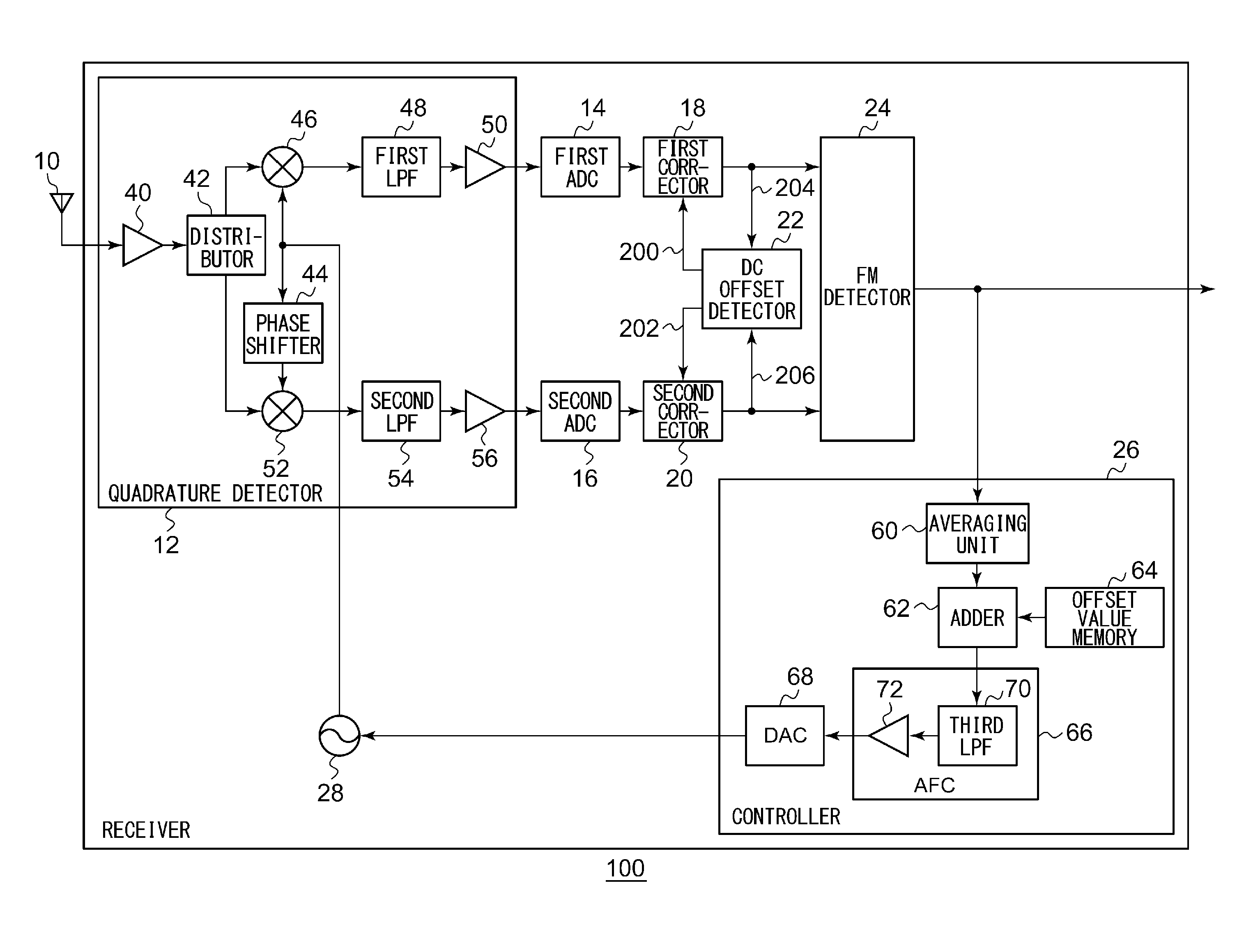
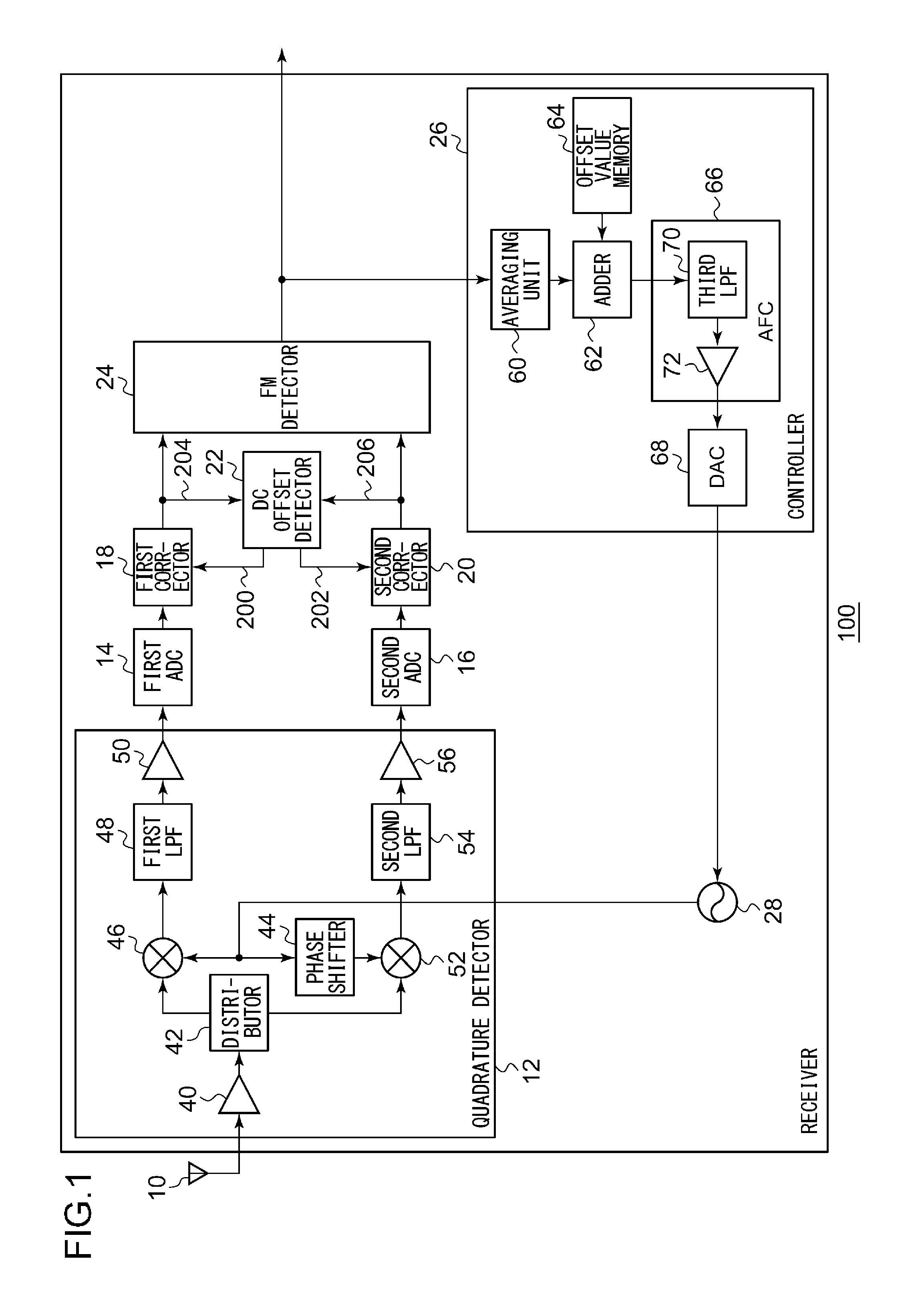
[0016]A summary will be given before describing the present disclosure in detail. A first embodiment of the present disclosure relates to a direct conversion type FM receiver. This FM receiver detects a DC offset by utilizing the characteristics of a baseband Lissajous waveform in a constant envelope modulation scheme in order to suppress a deterioration of a signal receiving performance due to DC offset components. As explained above, when a received signal is in an unmodulated state, and the frequency thereof is identical with that of a local oscillation signal, it becomes difficult to distinguish the received signal and the DC offset from each other, and the corrected I-phase baseband signal and the corrected Q-phase baseband signal become “0”. In order to suppress an occasion of such a false operation, the FM receiver of this embodiment executes the following processes.

[0017]The FM receiver performs FM detection on the corrected I-phase baseband signal and the corrected Q-phase ...

second embodiment

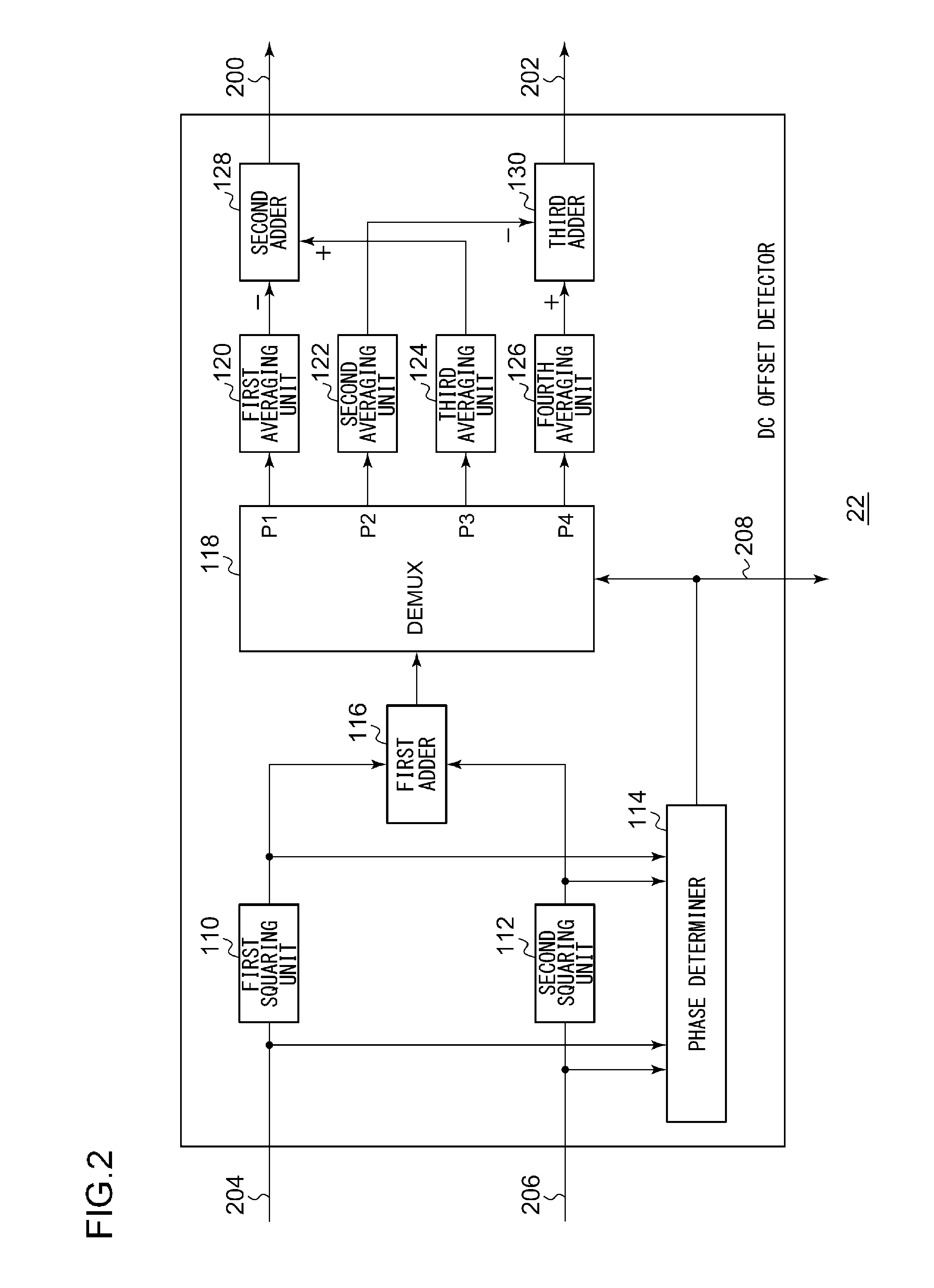
[0044]Next, an explanation will be given of a second embodiment. The second embodiment relates to a direct conversion type FM receiver like the first embodiment. According to the first embodiment, in order to suppress an occurrence of a false operation when the DC offset is detected, the frequency of the local oscillation signal is controlled after the offset is added to the detection signal. Conversely, according to the second embodiment, in order to suppress an occurrence of a false operation when the DC offset is detected, a distribution of the corrected I-phase baseband signal and the corrected Q-phase baseband signal which appear in each phase domain is monitored. When the distribution is non-uniform, the frequency of the local oscillation signal is changed. Consequently, an occurrence of a circumstance in which the phase signal keeps taking a constant value is suppressed.

[0045]FIG. 4 illustrates a structure of a receiver 100 according to the second embodiment. The receiver 100...


PUM


Abstract

A quadrature detector performs a quadrature detection on an FM signal based on a local oscillation signal, and outputs a baseband signal. A first corrector and a second corrector perform a correction on the baseband signal based on a DC offset correction value. The DC offset detector performs a polar coordinate conversion on the baseband signal, and derives the DC offset value in such a way that respective amplitudes in a plurality of phase domains defined on an IQ plane approximate one another. An FM detector performs an FM detection on the corrected baseband signal, and generates a detection signal. A controller controls the frequency of the local oscillation signal in such a way that a phase component having undergone the polar coordinate conversion by the DC offset detector is rotated.

Description

CROSS-REFERENCE TO RELATED APPLICATION[0001]This application is based upon and claims the benefit of priority from the prior Japanese Patent Application No. 2015-12458, filed on Jan. 26, 2015, the entire contents of which are incorporated herein by reference.BACKGROUND[0002]1. Field[0003]The present disclosure relates to a reception technology, and more specifically, to an FM receiver and an FM receiving method for receiving FM signals.[0004]2. Description of the Related Art[0005]A direct conversion type Frequency Modulation (FM) receiver converts an RF signal into a baseband signal by quadrature detection, and amplifies the baseband signal by an amplifier. When unnecessary Direct Current (DC) components are output by the amplifier, such DC components cause a DC offset, deteriorating the signal receiving performance of the receiver. In order to avoid such a performance deterioration, polar coordinate conversion is performed on an I-phase baseband signal and a Q-phase baseband signal...

Claims


Application Information

Patent Timeline
IPC IPC(8): H04L27/14H04L25/06
CPCH04L25/06H04L27/142
Inventor OKUHATA, YASUHIDE
Owner JVC KENWOOD CORP A CORP OF JAPAN
Why Eureka
Try Eureka