Unlock instant, AI-driven research and patent intelligence for your innovation.

Cleaning tool for a floor cleaning appliance

Inactive Publication Date: 2016-08-04
ALFRED KARCHER GMBH & CO KG
View PDF1 Cites 2 Cited by
  • Summary
  • Abstract
  • Description
  • Claims
  • Application Information

AI Technical Summary

Benefits of technology

This patent relates to a floor cleaning tool that has a carrying part that slides along the floor surface being cleaned when the cleaning cover reaches its maximum allowed wear. The carrying part is designed to evasively move to prevent damage to the floor surface and to prematurely indicate that the cleaning cover should be replaced. The tool also has a mechanically influenced signal transmitter that can detect a change in the signal and alert the user that the cleaning cover has reached its maximum wear. The carrying part and signal transmitter are only affected by the floor surface when the maximum wear is reached, ensuring that the carrying part and signal transmitter are not damaged during normal operation of the tool. The carrying body, spring body, and base body are made as a single plastic molded part, and the recess of the main body is easily assembled onto the carrying part. The technical effects of the patent are an improved floor cleaning tool that can reliably detect when the cleaning cover has reached its maximum wear without user intervention and prevent damage to the floor surface during use.

Problems solved by technology

This results in the carrying part and / or the signal transmitter being adversely affected by the floor surface upon further use of the cleaning tool.
This ultimately causes damage to the carrying part and / or the signal transmitter, which, in turn, leads to a change in the wireless signal provided by the signal transmitter.
It may, for example, be provided that when a maximum admissible degree of wear of the cleaning cover is exceeded, the signal transmitter is damaged or even destroyed by the floor surface or becomes detached from the carrying part.

Method used


Image

  • Cleaning tool for a floor cleaning appliance
  • Cleaning tool for a floor cleaning appliance
  • Cleaning tool for a floor cleaning appliance

Examples


Embodiment Construction

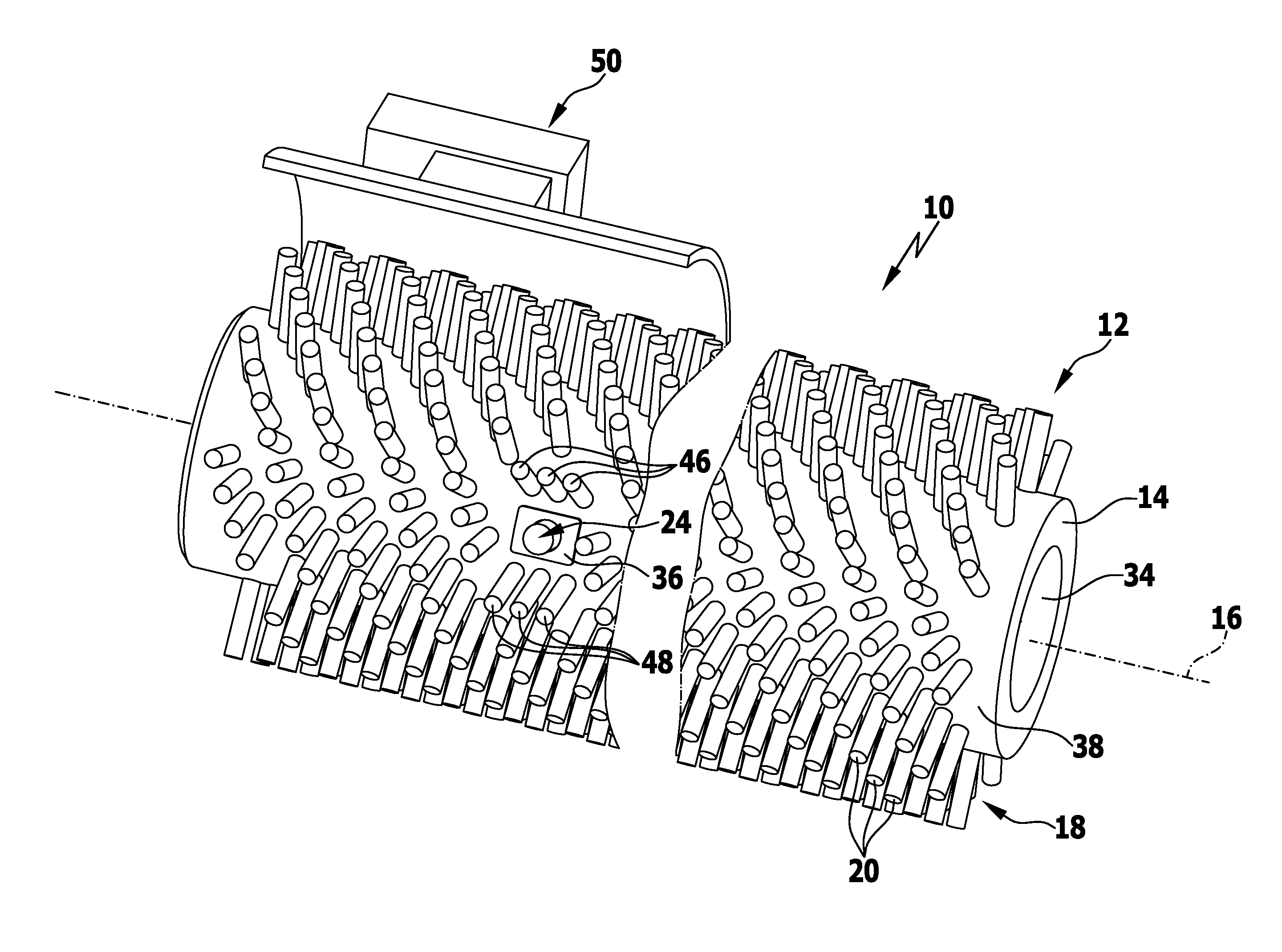
[0055]A first advantageous embodiment of a cleaning tool in accordance with the invention, which is denoted in its entirety by reference numeral 10, is shown schematically in FIGS. 1 to 7. The cleaning tool 10 is configured as roller brush 12 and has a hollow-cylindrical main body 14 which can be mounted on a floor cleaning appliance, known per se, for rotation about an axis of rotation 16.

[0056]The main body 14 carries on its outer side a cleaning cover which is configured in the form of a bristle cover 18 and comprises a large number of cleaning bristles 20 which protrude outwardly from the main body 14.

[0057]In the course of time, the cleaning bristles 20 wear away during use of the roller brush 12 and become shorter.

[0058]When a maximum admissible degree of wear has been reached, this can be wirelessly indicated to the user by a rigid signal transmitter 22. The signal transmitter 22 is configured in the form of a rigidly constructed transponder, in particular, in the form of a f...


PUM


Abstract

A cleaning tool for a floor cleaning appliance is provided, including a main body carrying a cleaning cover which is subject to wear, and including a signal transmitter which provides a wireless signal in dependence upon the degree of wear of the cleaning cover. To be able to detect in a cost-effective manner when a maximum admissible degree of wear of the cleaning cover is reached, the signal transmitter is of rigid construction and fixed to a movable carrying part, the carrying part being held on the main body and being movable from a normal position to an evasive position against a restoring force, the carrying part protruding further from the main body in the normal position than in the evasive position, and the carrying part and / or the signal transmitter contacting the floor surface to be cleaned when a maximum admissible degree of wear of the cleaning cover is reached.

Description

CROSS-REFERENCE TO RELATED APPLICATIONS[0001]This application is a continuation of international application number PCT / EP2014 / 067119 filed on Aug. 8, 2014 and claims the benefit of German application number 10 2013 111 330.3 filed on Oct. 14, 2013, which are incorporated herein by reference in their entirety and for all purposes.BACKGROUND OF THE INVENTION[0002]The invention relates to a cleaning tool for a floor cleaning appliance, comprising a main body carrying a cleaning cover which is subject to wear, and comprising a signal transmitter which provides a wireless signal in dependence upon the degree of wear of the cleaning cover.[0003]Floor cleaning appliances, for example, sweeping machines, scrubbing machines or floor polishing machines, comprise a cleaning tool with a main body carrying a cleaning cover. The cleaning cover may, for example, be configured in the form of a bristle cover, a polishing disk or a cleaning pad and is subject to increasing wear during use of the cle...

Claims


Application Information

Patent Timeline
IPC IPC(8): A47L11/40A46B13/00
CPCA47L11/4002A47L11/4041A46B15/001A46B13/001E01H1/056
Inventor SCHUETZ, MICHAELNONNENMANN, FRANKMERZ, JUERGENEGLER, CHRISTIANHAUSNER, THOMASORBAN, ATTILA
Owner ALFRED KARCHER GMBH & CO KG