
Aircraft landing gear and method

a technology for landing gear and aircraft, which is applied in the direction of seaplanes, floats, undercarriages, etc., can solve the problems of significant damage or personal injury, water landing with the wheels down, and water landing with the wheels extended,

Active Publication Date: 2016-08-04
E B ROBINSON
View PDF2 Cites 9 Cited by
  • Summary
  • Abstract
  • Description
  • Claims
  • Application Information

AI Technical Summary

Benefits of technology

The invention relates to a landing gear for an amphibious aircraft that can land on both water and land. The landing gear has a wheel and a deflector that creates a water-riding hull. The wheel can move between a retracted position and an extended position, and the deflector is designed to move with the wheel. The landing gear can be housed within the aircraft and is designed to move with the aircraft during operation. The technical effects of the invention include improved performance on water and land, reduced weight, and improved efficiency of the landing gear system.

Problems solved by technology

One cause of accidents in amphibious aircraft is landing in water with the wheels down.
A water landing with wheeled gear extended may be catastrophic: as the gear descends into the water, it may tend to function as an oar or paddle that generates a substantial overturning moment on the aircraft, such as may tend to flip the aircraft over on its nose (if the gear plunges into the water symmetrically) or to spin and flip the aircraft, possibly in cartwheel fashion, if one wheel catches the water before the other.
In either case the result may be very significant damage or personal injury, or both.
Alternatively, when the aircraft lands on terrain with the wheeled landing gear retracted, the effect may be that of a belly landing, with the possibility of doing significant damage to the aircraft hull (or pontoons).
Damage may similarly occur if one or another wheel of the landing gear extends, while one or more other wheels remain retracted.

Method used


Image

  • Aircraft landing gear and method
  • Aircraft landing gear and method
  • Aircraft landing gear and method

Examples


Embodiment Construction

[0042]The description that follows, and the embodiments described therein, are provided by way of illustration of an example, or examples, of particular embodiments of the principles, aspects or features of the invention. These examples are provided for the purposes of explanation, and not of limitation, of those principles and of the invention. In the description, like parts are marked throughout the specification and the drawings with the same respective reference numerals. The drawings may be taken as being to scale unless noted otherwise.

[0043]The terminology used in this specification is thought to be consistent with the customary and ordinary meanings of those terms as they would be understood by a person of ordinary skill in the aircraft industry in North America. The Applicant expressly excludes all interpretations that are inconsistent with this specification, and, in particular, expressly excludes any interpretation of the claims or the language used in this specification ...


PUM


Abstract

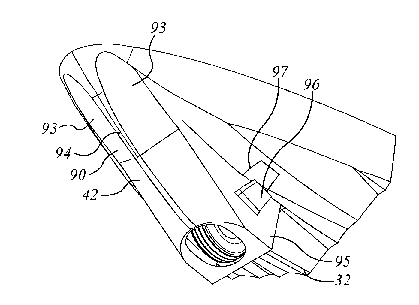
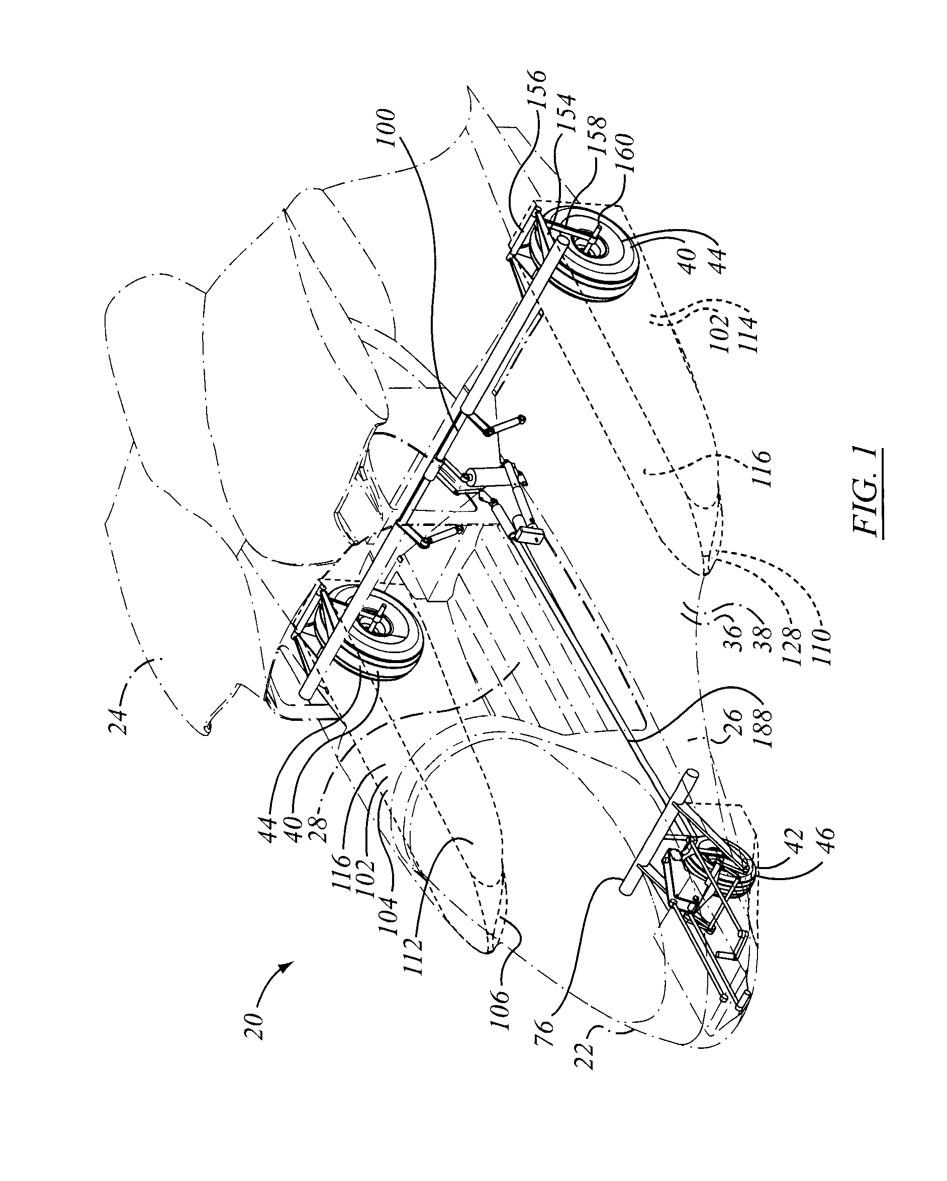
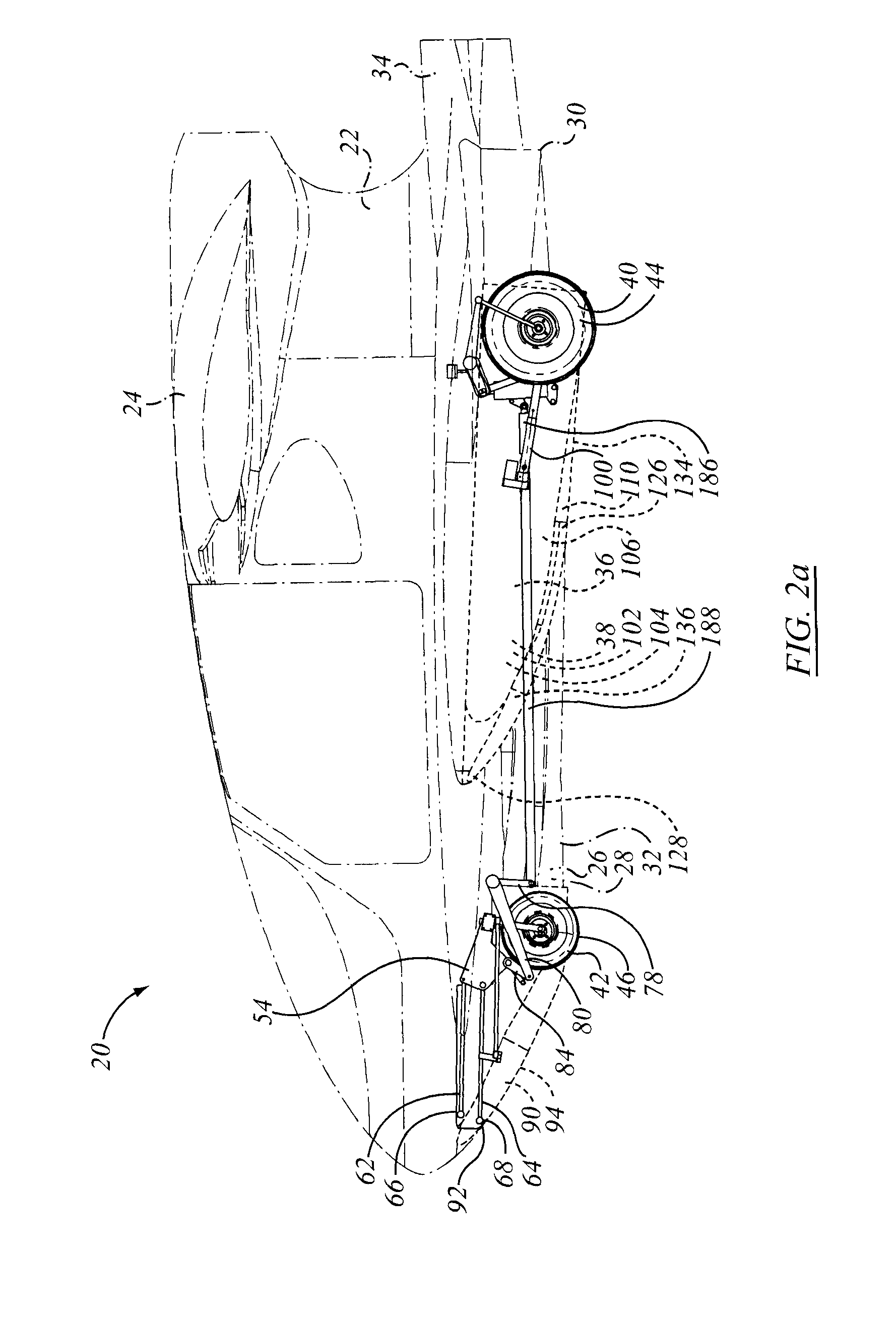
An amphibious aircraft has a tricycle landing gear that is movable between a retracted, or up, position and an extended, or down, position. Each member of the landing gear is protected in the forward direction by a hydrodynamic protector, or vane, or shoe, such as may tend to create lift when brought into engagement with water, as during landing. The landing gear protector vanes may be mounted to move with extension and retraction of the landing gear. The landing gear wheels may protrude to extend partially downwardly proud of the sole of the shoe. The landing gear actuator and transmission may operate all gear in concert. The shoes may include sacrificial wear members for ground engagement in the event of an inadvertent gear-up landing on terrain.

Description

FIELD OF THE INVENTION[0001]This invention relates to the field of amphibious aircraft and to landing gear for aircraft.BACKGROUND[0002]Amphibious aircraft are designed to land either on water or on land. Amphibious aircraft may typically be of two types, namely those with a pair of pontoons; and true flying boats with a water-tight hull. For fixed-wing aircraft, whether using skis or a hull, there will be a forward, or leading, direction, and a rearward or trailing direction.[0003]In either instance it is possible to land, or to attempt to land, a fixed wing amphibious aircraft with the landing gear in an inappropriate configuration. That is, it is possible to make a landing on terrain with the wheeled landing gear retracted; and it is possible to make a landing on water with the wheeled landing gear extended. One cause of accidents in amphibious aircraft is landing in water with the wheels down. A water landing with wheeled gear extended may be catastrophic: as the gear descends i...

Claims


Application Information

Patent Timeline
Patent Type & Authority Applications(United States)
IPC IPC(8): B64C25/66
CPCB64C25/54B64C25/04B64C25/66B64C35/008B64C25/20
Inventor ROBINSON, ERIC BRIAN
Owner E B ROBINSON
Learn More