Actuator for Electric Park Brake System and Self-locking Mechanism Thereof

a technology of brake system and actuator, which is applied in the direction of actuator, brake actuating mechanism, slack adjuster, etc., can solve the problem of low transmission efficiency and achieve the effect of improving efficiency

Inactive Publication Date: 2016-08-04
JOHNSON ELECTRIC SA
View PDF8 Cites 15 Cited by
  • Summary
  • Abstract
  • Description
  • Claims
  • Application Information

AI Technical Summary

Benefits of technology

[0039]In the actuator described above, when the torque is transmitted from the motor through the speed reduction device to the output member, the output gear drives the movable wheel to rotate therewith through the driving blocks, the spring frictionally rotates relative to the fixed wheel along with the movable wheel. When the output member rotates under an external force to generate a trend of releasing the brake, the torque is transmitted from the output member to the movable wheel, the rotating movable wheel drives the spring to rotate in the winding direction of the spring, which causes the spring to decrease in its inner diameter and hold on the fixed wheel to thereby prevent the movable wheel from further rotation, which in turn prevents the output member from further rotation, thus achieving the self-locking function. The actuator of the present invention has an enhanced efficiency in comparison with the lead screw actuator.

Problems solved by technology

However, the lead screw transmission results in low transmission efficiency.

Method used


Image

  • Actuator for Electric Park Brake System and Self-locking Mechanism Thereof
  • Actuator for Electric Park Brake System and Self-locking Mechanism Thereof
  • Actuator for Electric Park Brake System and Self-locking Mechanism Thereof

Examples


Embodiment Construction

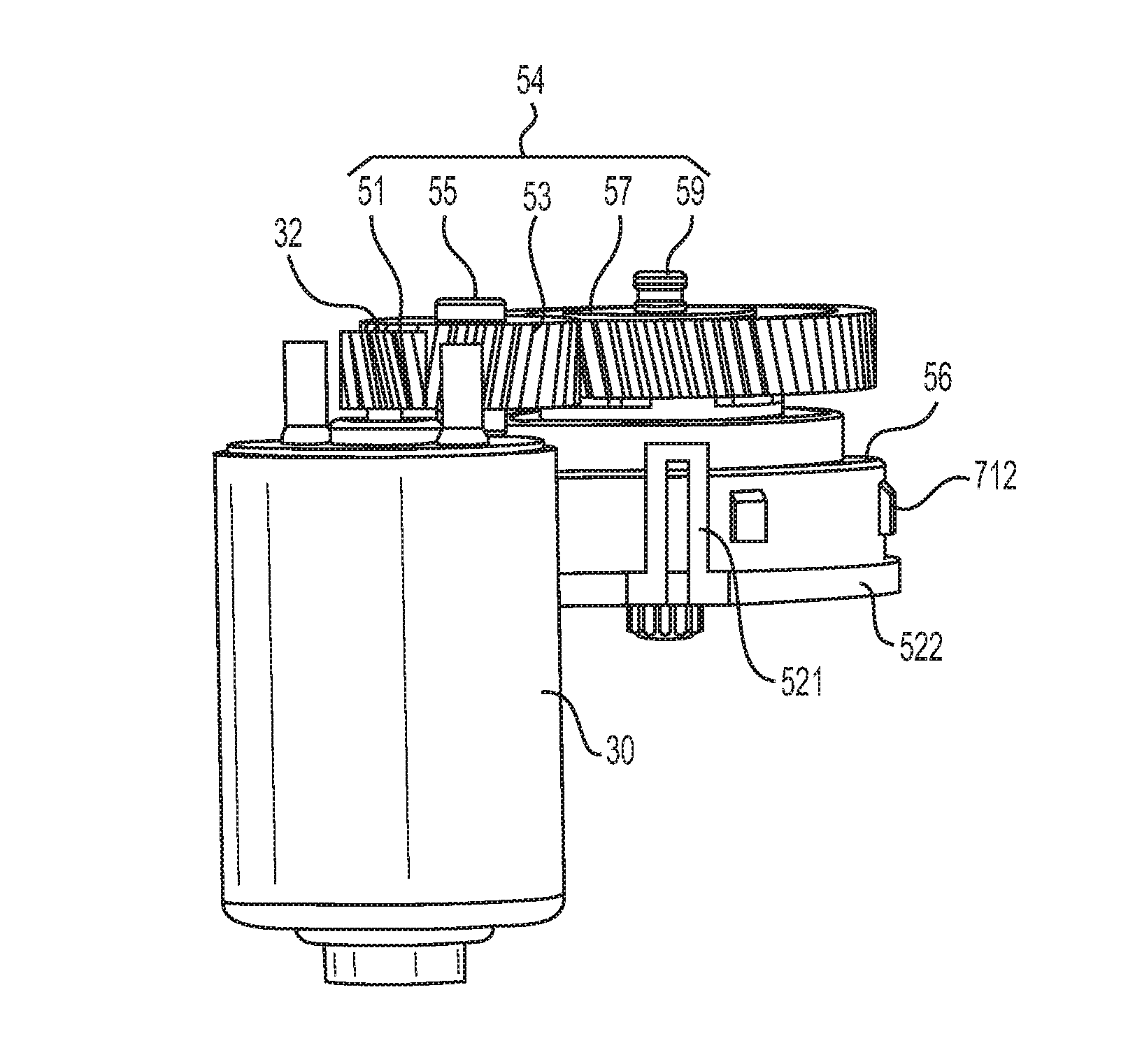
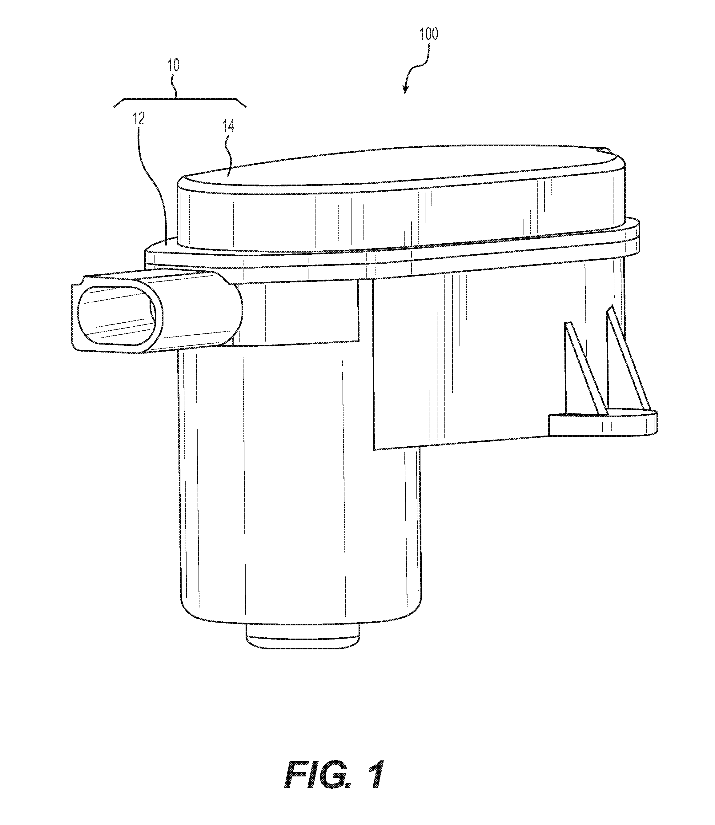
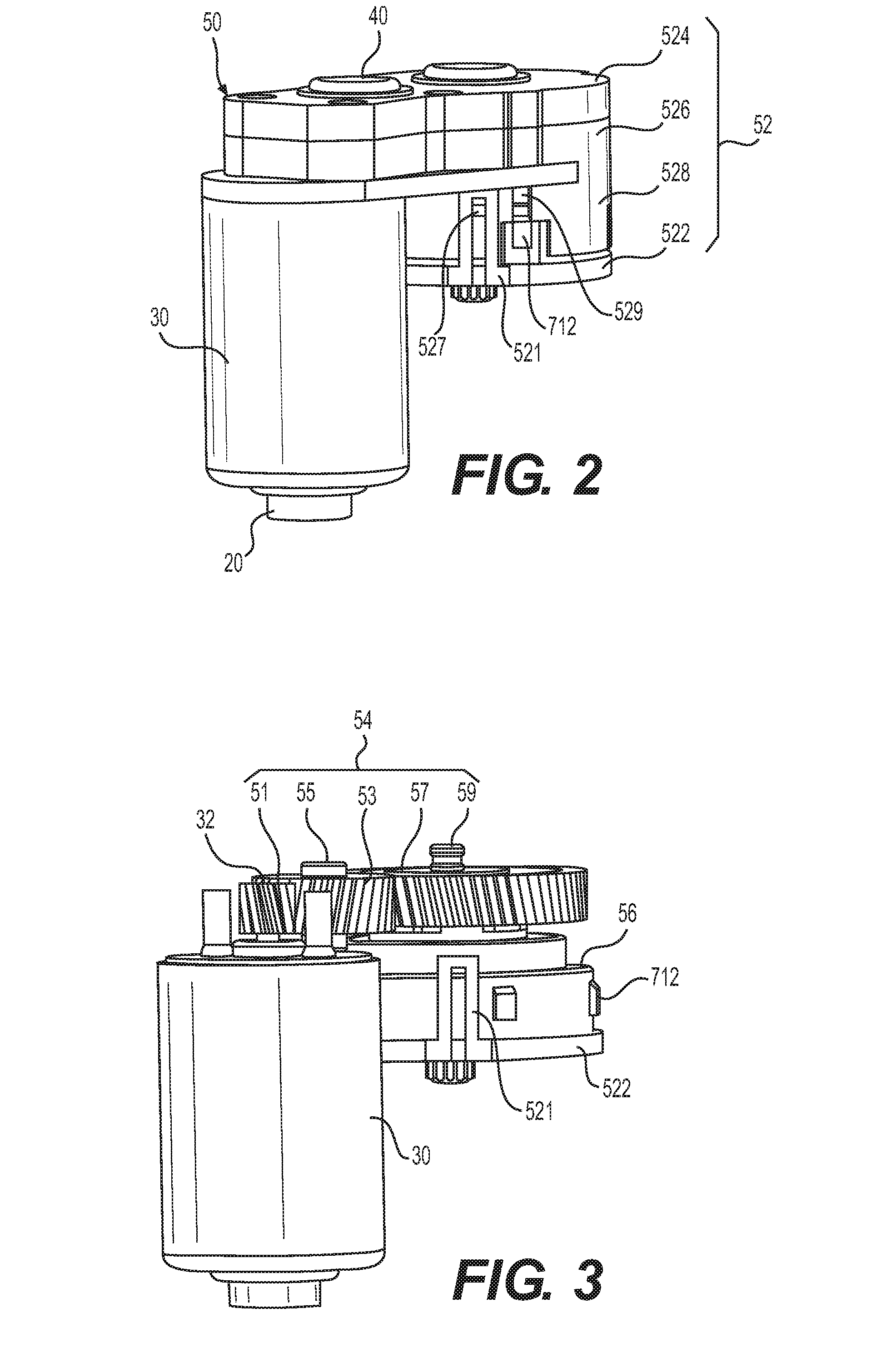
[0081]Referring to FIG. 1 and FIG. 2, an actuator 100 for an electric parking brake (EPB) system in accordance with the present invention includes an outer housing 10, a motor 30 received in the outer housing 10, a speed reduction device 50 connected with the motor 30, and an output member 80 (see FIG. 5) connected with the speed reduction device 50.

[0082]The outer housing 10 includes a house base 12 and a cover body 14 connected to a top side of the housing base 12. The cover body 14 and the housing base 12 cooperatively form a receiving space for receiving the motor 30 and the speed reduction device 50 therein. Referring also to FIG. 3 through FIG. 5, the speed reduction device 50 includes a housing 52, and a transmission mechanism 54, a planetary gear mechanism 56 and a self-locking mechanism 58 that are received in the housing 52. The self-locking mechanism 58 connects the transmission mechanism 54 and the planetary gear mechanism 56. The motor 30 and the planetary gear mechanis...


PUM


Abstract

An actuator for an electric parking brake system includes a motor, an output member, and a speed reduction device. The speed reduction device includes a transmission mechanism and a self-locking mechanism. The self-locking mechanism includes a fixed member, first and second rotating bodies, and a spring. The second rotating body transmits torque to the output member via a planetary gear mechanism. The spring prevents the brake from driving the motor.

Description

CROSS REFERENCE TO RELATED APPLICATIONS[0001]This non-provisional patent application claims priority under 35 U.S.C. §119(a) from Patent Application No. 201510050697.8 filed in The People's Republic of China on Jan. 30, 2015, the entire contents of which are hereby incorporated by reference.FIELD OF THE INVENTION[0002]This invention relates to an electric parking brake system, and in particular to an actuator for the electrical parking brake system and its self-locking mechanism.BACKGROUND OF THE INVENTION[0003]A parking brake system of a car is mainly used to keep the car motionless when it is parked. The traditional parking brake system is hand-operated and thus named “handbrake”. The driver needs to control the force of pulling the handbrake based on experience.[0004]Electric parking brake (EPB) systems have been gradually replacing the traditional mechanical handbrakes. The existing EPB system includes a motor, an actuator connected with the shaft of the motor, and a brake mount...

Claims


Application Information

Patent Timeline
Patent Type & Authority Applications(United States)
IPC IPC(8): F16D65/18
CPCF16D65/18F16D2125/40F16D2125/48F16D2121/24F16D65/50F16D2127/06
Inventor WATZEK, MICHAELZHANG, YUAN CHUNNIE, JIN ANQI, FA YUNCHEN, YA JIEQIN, RUI FENGKAESER, MICHAEL
Owner JOHNSON ELECTRIC SA
Why Eureka
Try Eureka